
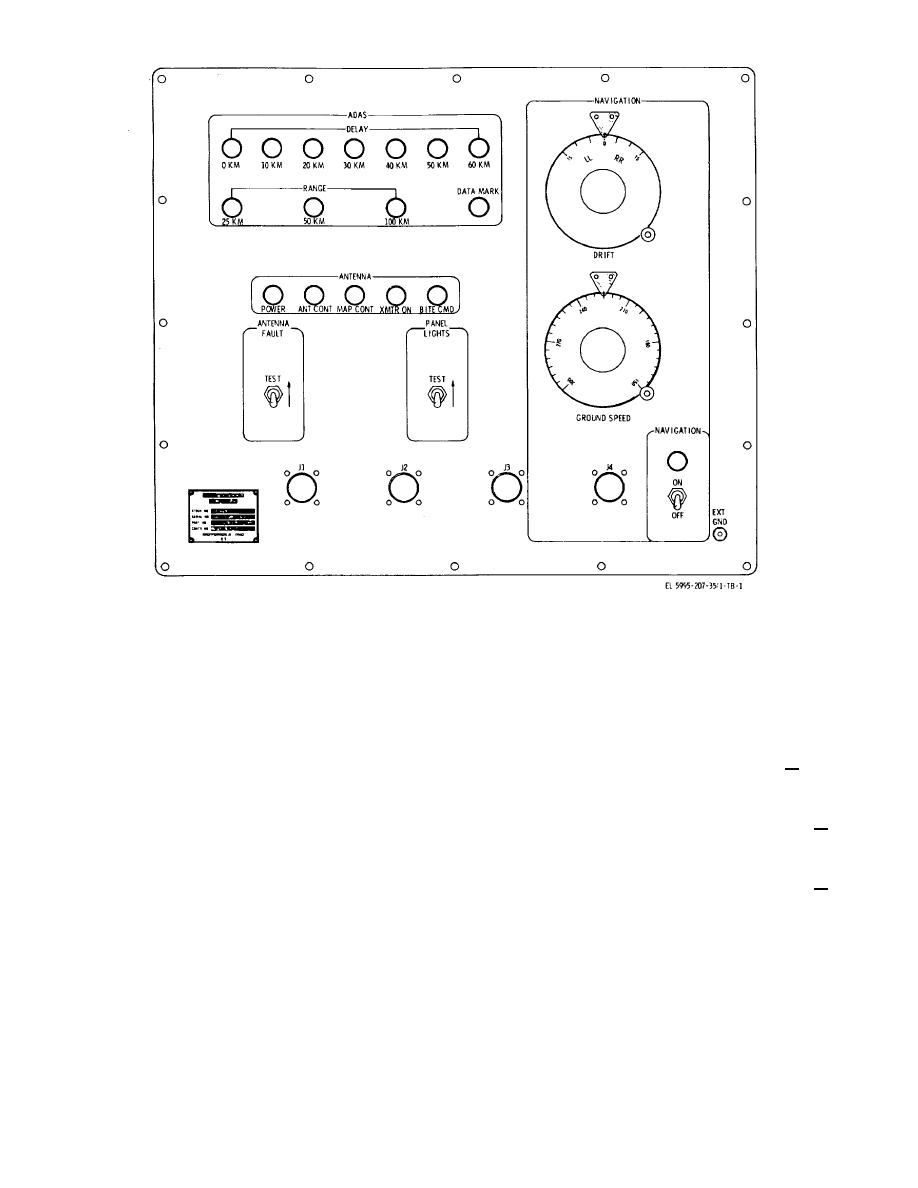
Figure 1. Simulator-Monitor SM-567/APS-94D, controls, indicators, and connectors.
a. Identification.
2. Reporting of Technical Bulletin Improvements.
Nomenclature......... Simulator-Monitor SM-567/APS-94D
The
reporting
of
errors,
omissions,
and
Size ........................ 19.25 H x 24.25 W x 21.13 D inches
recommendations for improving this bulletin by the
Weight .................... 53 lbs.
individual user is encouraged. Reports should be
Reference........................................ TM 11-5995-207-12
submitted or DA Form 2028 (Recommended Changes to
TM 11-5995-207-45
Publications) and forwarded direct to commanding
General, U.S Army Electronics Command, ATTN
b. Specifications
AMSEL-ME-NMP-EM, Fort Monmouth, N.J., 07703
Input power requirements
AC 115 Vac + 10%, 400
Hz, 1 phase
3. Description. Simulator-Monitor SM-567/APS 94D is
portable special test equipment for Radar Surveillance
Navigation ground speed
Maximum meter
Set AN/APS-94D. The instrument consists of a panel
coarse position check
indication at 225 + 10
assembly and three cable assemblies housed in a steel
dial reading.
case. the presence of airborne data annotation system
(ADAS) and antenna signal in the circuits of the AN
Navigation ground speed
Minimum meter
'APS-94D are indicated by the instrument when it is
fine position check
indication at 225 + 0.5
connected to the AN APS-94D for bench servicing. The
dial reading.
instrument provides an antenna fault test function for the
AN, APS-94D and supplies navigation inputs to the AN,
Navigation drift
Maximum meter
APS-34D, normally supplied by aircraft equipment.
coarse position check
indication at 0+5 dial
Additional data is listed in a through c below.
reading.
Navigation drift
Minimum meter
fine position check
indication at 0+ 0.33 dial
reading.
c. Program Data.
Time required for calibration ........................ 1 hr (approx)
Calibration level............................................ Maintenance
2

