
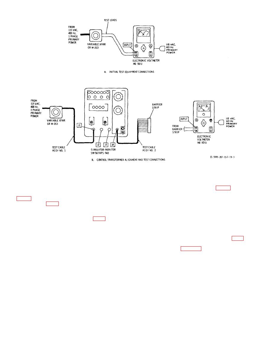
Figure 3. Test setup.
b
Adjustment No. 1.
8. Navigation Ground Speed Transformer BI Coarse
Position. a. Performance Check.
(1) Disassemble dial lock (fig. 1) and turn
NAVIGATION GROUND SPEED dial (five revolution
(1) Be sure NAVIGATION GROUND SPEED dial
maximum) to obtain maximum indication on electronic
transformer B1 (fig. 4).
(2)
Reassemble dial lock.
(2) Install jumper wires between terminals C and
J, A and E, and A and H of barrier strip (fig. 2).
c. Adjustment No. 2.
(3) Connect electronic voltmeter to terminals C
(1) Set NAVIGATION GROUND SPEED dial at
and F of barrier strip with test leads.
225 and lock dial at this setting with dial lock (fig. 1).
(4)
Energize 115 vac, 400 Hz primary power
(2) Refer to figure 4. Loosen the three clamp
circuit.
screws that secure case of transformer B1.
(5) Observe electronic voltmeter and carefully set
(3) Observe electronic voltmeter and slowly turn
NAVIGATION GROUND SPEED dial for maximum
transformer case for maximum indication on electronic
indication on electronic voltmeter. If maximum indication
cannot be obtained, perform adjustment No. 1 in b
below.
(4) Tighten the three clamp screws that secure
case of transformer B1.
(6) Check NAVIGATION GROUND SPEED dial
indication. The dial indication should be 225 10. If dial
indication is incorrect perform adjustment No. 2 in c
below.
5

