
CALIBRATION PROCESS
8. Preliminary Procedure
It is recommended that personnel familiarize themselves with the entire procedure
before performing calibration,
d. Insulate unused power cord plug on test
a. Position test instrument on its back.
b. Remove SB-3100/ARM-109 Power Distribution
instrument Power Distribution Panel.
CAUTION
Panel to gain access to power cables.
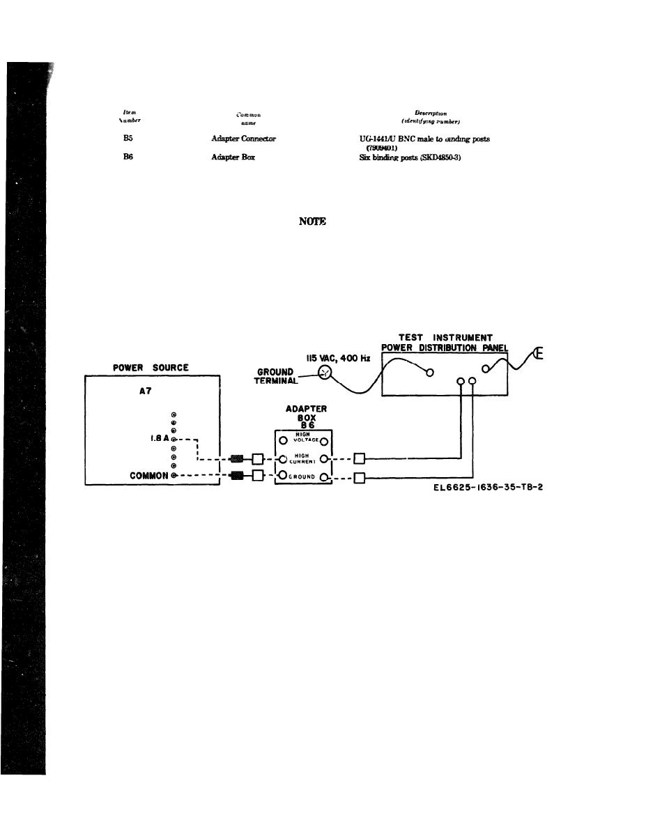
c. Connect TS-2354/ARM-109 power cord to 115/
Power source must be within 5V rms of
Vrms, 400 Hz source. Refer to figure 2 for typical
115V, 1 Hz of 400 Hz and waveshape must
be sinusoidal for correct calibration.
hookup.
Figure 2 Typical 400 Hz power application.
justment before continuing with the calib-
e. Check zero indicator of the Test instrument
ration procedure. When the performance
METER and adjust if necessary.
check is not within tolerance and the
WARNING
adjustment cannot bring it into tolerance,
HIGH VOLTAGE is used during the
the deficiency must be corrected before
performance of this calibration. DEATH
continuing with the procedure.
ON CONTACT may result if personnel fail
to observe safety precautions.
(1) Position the test instrument controls as
NOTE
follows:
The following paragraphs are divided into
(a) POWER switch to ON.
subparagraph a, performance check, and
(b) OFF/SELF-TEST ON switch to ON.
subparagraph b, adjustments. When the
performance check is within tolerance, do
(c) FUNCTION switch to 1.
not perform the corresponding adjustment.
(2) Connect electronic voltmeter (A1) to connec-
When the performance check is not within
tor J1, pin 33 (fig. 3) and chassis ground using test
tolerance, perform the corresponding ad-
lead set (B4).

