
Table 3 Meter Test Settings
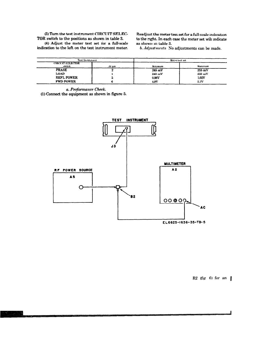
Figure 5 Input power check test setup
between 6 and 8 (4 and 6) scale, divisions.
(2) Adjust Rf power source (A5) to a frequency of
b. Adjustments.
2.000 MHz.
(1) Deenergize test instrument and remove
(3) Turn the test instrument CIRCUIT SELEC-
TS-2352/ARM-109 from its protective case.
TOR switch to INPUT POWER.
(2) Perform steps a (1) through (4) above.
(4) Key the rf power source and adjust the output
(3) Adjust potentiometer
for 70V Rf (50) as indicated by multimeter (A2).
indication of 7 (5) on the meter (R)
(5) The test instrument METER shall indicate

