
(6) SWEEP TIME (SEC) switch to 100-
10.
(7) SWEEP TIME (SEC) VENIER control
to LINE SYNC.
(8) INT SQ WAVE FREQ control fully
counterclockwise.
(11) BLANKING (rear panel) to ON.
(10) FUNCTION START STOP pushbut-
ton pressed.
a. Performance Check.
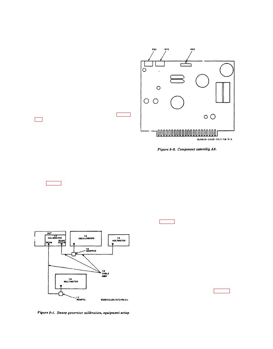
(1) Connect equipment as shown in figure
(2) Position UUT controls as follows:
(a) SWEEP' SELECTOR switch to CW.
(b) FUNCTION START-STOP pushbut-
ton pressed.
(c) START/CW control to 73 V on cali-
brator scale.
(3) Set calibrator FUNCTION SELECTOR
switch to SWP REF AM.
( b ) MANUAL SWEEP control fully
(4) Multimeter indicates between 72.9 and
clockwise.
73.1 vdc.
( 2 ) Connect multimeter to calibrator
SCOPE ACVM connector with cable assembly
b. Adjustments Adjust UUT 75 V RAMP ADJ
(1-8) and adapter (1, 7).
R75 (fig. 3-2) for multimeter indication of 73.0
vdc.
(3) Set calibrator FUNCTION SELECTOR
switch to ANODE/START AMP.
(4) Multimetor indicates between -0.010
and +0.010 vdc (8690A), or -0.100 and 0+.100
a. Perfomance Check.
vdc (8690B) .
(1) Position UUT controls as follows:
b. Adjustments. Adjust UUT RAMP ZERO
( a ) SWEEP SELECTOR switch to
ADJ R53 (fig. 3-2) for multimeter indication of
MANUAL.
0.00 vdc.
.
a. Performance Check.
(1) Turn UUT MANUAL SWEEP control
fully counterclockwise.
(2) Set calibrator FUNCTION SELECTOR
switch to HELIX FDBK STOP RMP.
(3) Multimeter indicates between -0.010
and +0.010 vdc (8690A). or -0.400 and +0.400
vdc 8690B ) .
b. Adjustments. Adjust UUT R50 (fig. 3-2)
for multimeter indication of 0.00 vdc.
a. Performance Check.
16

