
(e) SWEEP S E L E C T O R switch to
MANUAL.
( f ) MANUAL SWEEP control fully
counterclockwise.
(2) Position UUT #1 controls as follows:
(a) SWEEP switch to PRESET.
(b) SELECT-STANDBY-OFF switch to
SELECT and release.
(c) START and STOP adjustments fully
counterclockwise.
(3) Multimeter indicates less than 3.0 vdc.
(4) Turn sweep oscillator
MANUAL
SWEEP control fully clockwise.
(5) Multimeter indicates less than 3.0 vdc.
(6) Turn UUT #1 START and STOP ad-
justments fully clockwise.
(7) Multi meter indicates greater than 73.0
vdc.
MANUAL
oscillator
(8) Turn
sweep
SWEEP control fully counterclockwise.
(9) Multimeter indicates greater than 73.0
vdc.
(11) Oscilloscope (l-8) displays square
(10) Remove calibrator from UUT cavity
wave.
#1 and install in cavity #2.
(12) Release sweep oscillator INT SQ
(11) Repeat steps (1) through (9) above
WAVE pushbutton.
with UUT #2 controls.
b. Adjustments. No adjustments can be made.
(12) Remover. calibrator from UUT cavity
#2 and install in cavity #3.
( 13) Repeat steps (1) through (9) above
a. Performance Check.
with UUT #3 controls.
(1) Position sweep oscillator controls as fol-
b. Adjustments. No adjustments can be made.
lows :
(a) LINE switch to RF.
( b ) All AMPLITUPE MOD pushbut-
tons released.
a. Performance check.
(c) ALC pushbutton released.
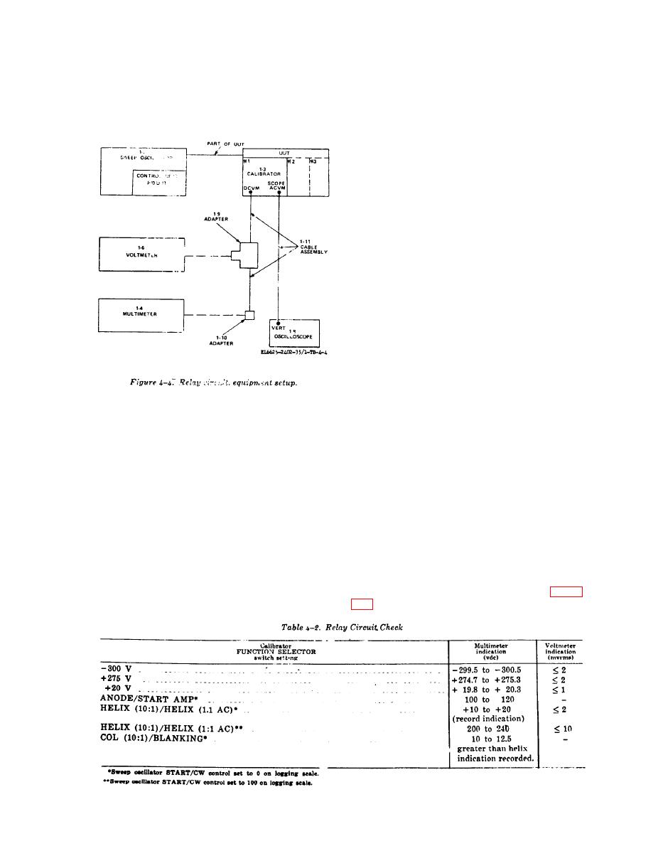
(1) Connect equipment as shown in figure
(d) FUNCTION START-STOP pushbut-
ton pressed.
27

