
Frequency (GHz)
Model number
8693A
8697A
H01-8694A H02-8694A
8695A
8692A
opt. 200
8664A
8696A
8693A
8691A
40.00
- E l m - 18.00
26.90
4.000
6.750
12.40
12.40
8.000
2.50
2.000
38.65
11.86
10.60
17.44
25.65
7.600
3.800
6.425
11.96
2.39
1.900
37.30
16.88
24.80
11.32
10.20
7.200
6.100
11.52
3.600
2.28
1.800
35.95
9.800
23.95
16.32
10.78
6.800
5.775
11.08
3.400
2.17
1.700
34.60
23.10
15.76
9.400
10.24
5.450
10.64
3.200
6.400
2.06
1.600
33.25
22.25
15.20
9.700
9.000
5.125
3.000
6.000
10.20
1.500
1.95
31.90
14.64
21.40
9.160
8.600
2.800
5.600
4.800
9.760
1.84
1.400
14.08
20.55
30.55
8.620
8.200
4.475
2.600
5.200
9.320
1.73
1.300
29.20
13.52
19.70
7.800
8.080
2.400
4.800
4.150
8.880
1.62
1.200
12.96
27.85
18.85
7.400
7.540
2.200
4.400
3.825
8.440
1.51
1.100
26.50
7.000
18.00
12.40
7.000
2.000
4.000
3.500
8.000
1.40
1.000
1
Tolerance for each indication is 0.8%.
2
Refer to paragraph 26, section III, including table 68 and figure 60 in TM 9-4931-294-15/1 for the calibration test setup for 8695A, 8696A and
8897A RF plug-in units.
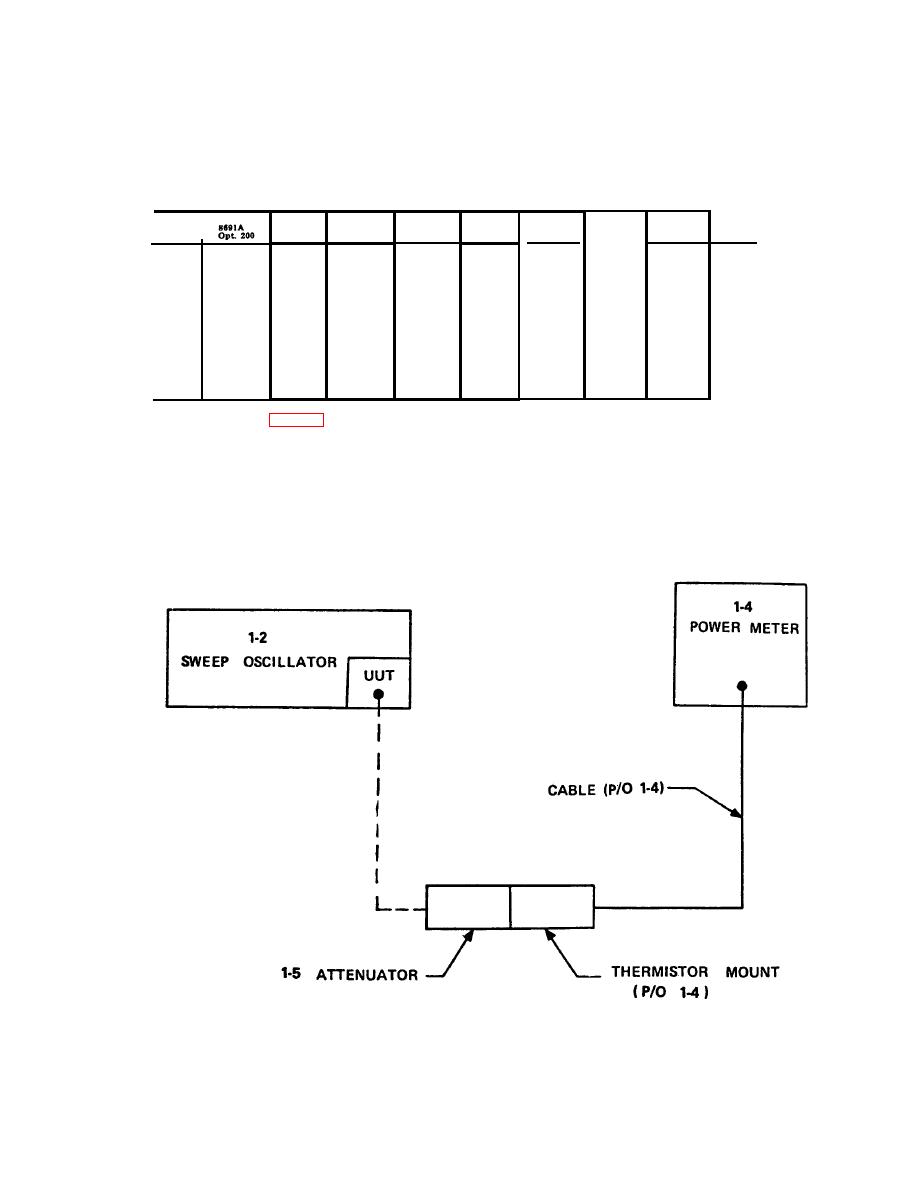
(2) Turn UUT POWER LEVEL control ful-
b Adjustments. No adjustments can be made.
ly clockwise.
5-5. RF Output
(3) Slowly turn sweep oscillator START/
a. Performance Check.
CW control across the entire frequency range.
Record the minimum and maximum power meter
(1) Connect equipment as shown in figure
(1-4) indications.
EL6625-2402-35/1-TB-5-2
Figure 5-2. RF output calibration, equipment setup.
31

