
personnel to test and troubleshoot servomotors and overload protection circuits in the AN. FRT-76 and AN FRT-77.
The subassemblies under test are activated by stimuli, generated in the transmitter test set, which simulate actual
operating conditions. A front panel meter and indicator are provided for monitoring. The transmitter test set overall
assembly is housed in an aluminum transit case. The transit case consists of a base and detachable cover. The cover
contains a removable plate which stores the accessory items supplied with the transmitter test set such as cables. The
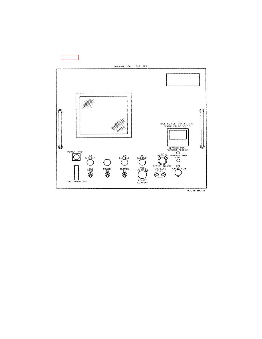
plate is secured to the cover by four fasteners. All operating controls of the transmitter test set are mounted on the front
panel assembly. Two handles are provided on the front panel assembly for convenience in removal of the transmitter
test set overall assembly from the transit case for servicing. The front panel controls and indicators of the transmitter
test set are illustrated in figure 1. Additional data is listed in a, b, and c below.
Figure 1. Transmitter test set controls and indicators.
a. Identification.
Nomenclature.............................................................................................................
Transmitter Test Set
Litcom model 4400.
Size ...........................................................................................................................
21 1/2 by 22 by 24 1/2
Weight .......................................................................................................................
70 lbs (approx)
b. Specifications.
Input requirement .......................................................................................................
103.5 to 126.5 volts ac, 54 to 66
Hz, single-phase.
Power supply output voltage ......................................................................................
+24 volts, de (+ 2 percent)
c. Program Data.
Calibration interval .....................................................................................................
In accordance with TB 750-236
Time required for calibration ......................................................................................
30 minutes.
Calibration level .........................................................................................................
Maintenance
4. General Instructions
a. Calibration Reporting. During the performance of the calibration procedures included in this manual,
annotate DA Form 2416 (Calibration Data Card) in accordance with TM 38-750.
procedures.
c. Unit Under Test. Transmitter test set will be referred to as "unit under test" throughout this procedure.
2

