
TB 11-6625-2713-50
(2) Set time-mark generator to 1 mS markers.
(3) Adjust TI LEVEL control for stable display and adjust HORIZ POSITION
control to align second marker on second vertical graticule line on crt. If 10th marker is not
displayed within 1.5 minor divisions of 10th vertical graticule line, perform b(1) below.
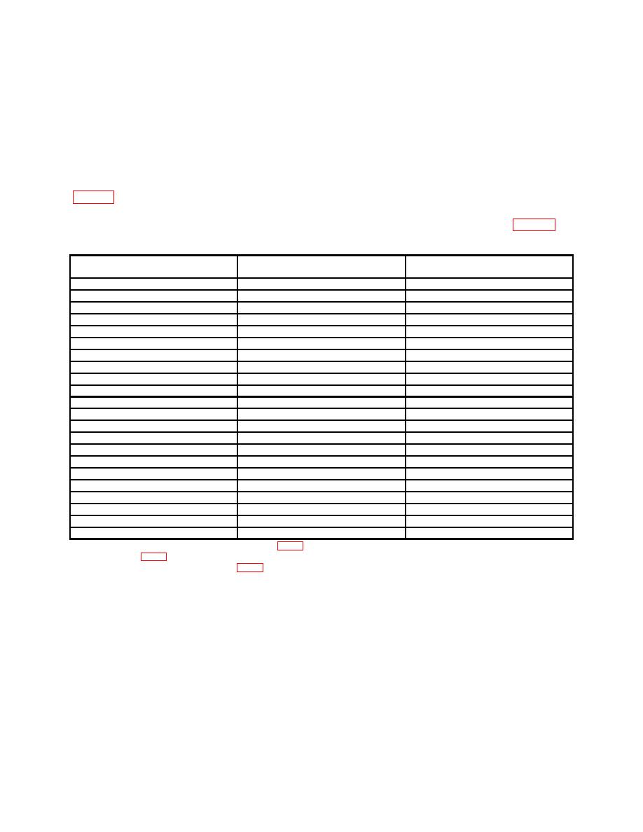
(4) Repeat technique of (2) and (3) above for TI TIME/DIV switch settings listed in
graticule line. If either 10th (1/div) or 19th (2/div) marker is not within 1.5 minor
divisions of 10th vertical graticule line, perform appropriate adjustments listed in table 6.
Table 6. Normal and Delayed Sweep Rates
Test instrument TIME/DIV
switch setting
Time-mark generator settings
Markers per division
.1 uSEC1
.50 nS
2
2. uSEC2
.1 uS
2
.5 uSEC
.5 uS
1
1 uSEC2
1 uS
1
2 uSEC
1 uS
2
5 uSEC
5 uS
1
10 uSEC
10 uS
1
20 uSEC
10 uS
2
50 uSEC
50 uS
1
.1 mSEC
.1 mS
1
.2 mSEC
.1 mS
2
.5 mSEC
.5 mS
1
1 mSEC3
.1 mS
1
1 mSEC
1 mS
1
2 mSEC
1 mS
2
5 mSEC
5 mS
1
10 mSEC
10 mS
1
20 mSEC
10 mS
2
50 mSEC
50 mS
1
.1 SEC
.1 s
1
.2 SEC
.1 s
2
.5 SEC
.5 s
1
1Alternately
adjust A1A2C9, A1A2C8, and A1A2C10 (fig. 4) for two cycles per Division.
2Adjust
A3A2C1 (fig. 4) to align each marker behind each major graticule line.
3Pull X10 Magnifier and adjust A1A2R1C (fig. 7) to align each marker behind each major graticule line.
(5) Set TI horizontal mode switch to DLY'D.
(6) Set TI TIME/DIV switch to 2 MSEC and DELAYED SWEEP to 1 MSEC.
(7) Set time-mark generator to 1 mS markers.
(8) Align second marker with second major vertical graticule line. If 10th marker is
not displayed within 1.5 minor divisions at 10th vertical line, perform b(2) below.
(9) Set TI TIME/DIV switch to 2 SEC and DELAYED SWEEP to 1 SEC and
repeat technique of (8) above, except perform b(3) below.
16

