
TB 11-6625-2734-50
(3) Turn TI mV/DIV switch to 100.
(2) Adjust R335 (fig. 2) for no trace shift when
(4) Adjust ac calibrator frequency for 1 kHz and
mV/DIV VARIABLE control is turned throughout its
amplitude for 6 divisions of vertical deflection on
range.
oscilloscope (A3) crt. If ac calibrator does not indicate
(3) Adjust R325 (fig. 2) until trace is centered on
between 0.205737 and 0.218463 volt rms, perform b
oscilloscope crt.
10. Vertical Gain. a. Performance Check.
below.
(5) Repeat technique of (3) and (4) above for TI
(1) Remove pulse generator (A4) from TI and
mV/DIV switch settings and a calibrator indications listed
install trigger recognizer (A6).
in table 4. Ac calibrator will indicate within limits
(2) Connect a calibrator (A1) to sampling head
specified.
(A7), using cable and adapter (B1 and B3).
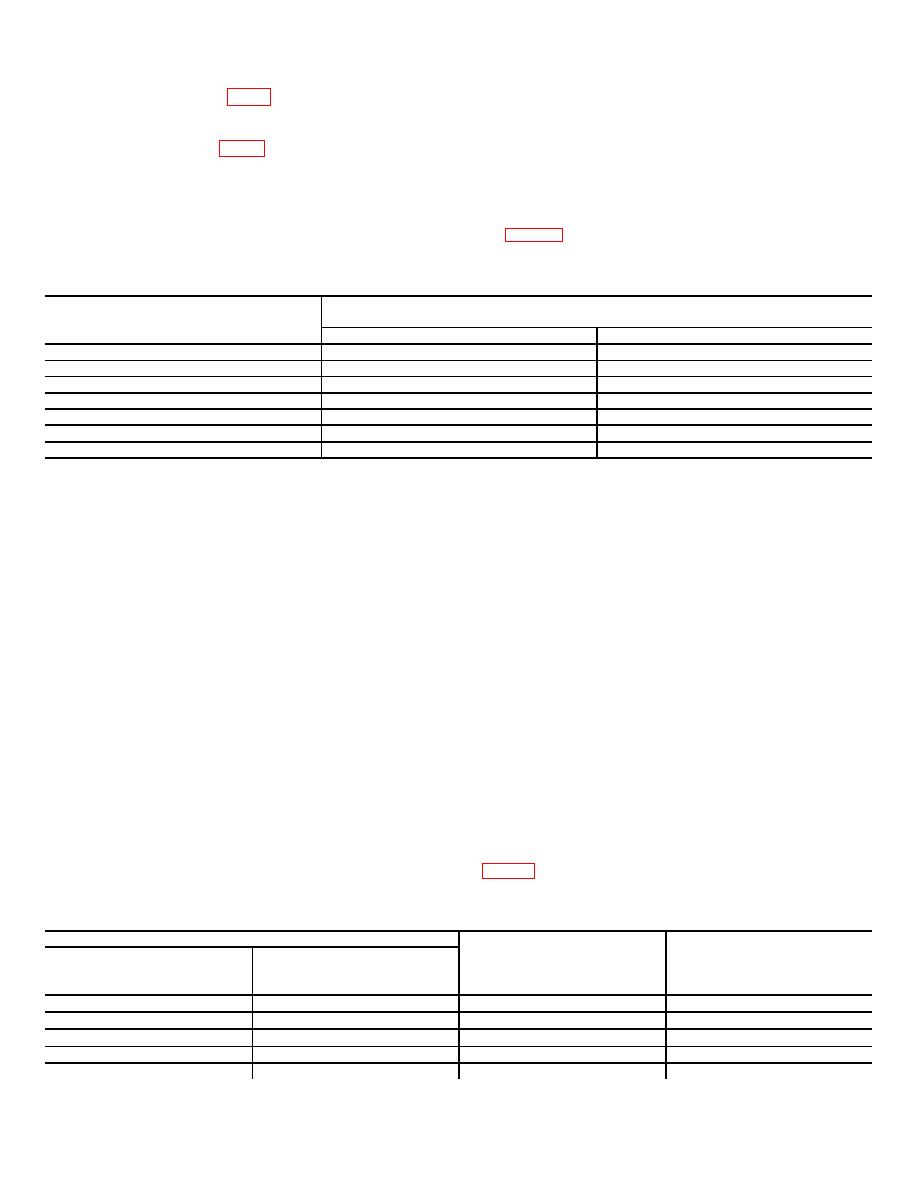
Table 4. Gain Accuracy Check
TI
Ac calibrator indications
mV/DIV switch
(rms)
settings
min
Max
500
1.01868 v
1.092312 v
200
0.411474 v
0.436926 v
50
0.102868 v
0.1092312 v
20
41.1474 mv
43.6928 mv
10
20.5737 mv
21.8463 mv
5
10.2868 mv
10.9232 mv
2
4.11474 mv
4.36926 mv
(3) Position TI controls as listed in (a) through
b. Adjustments.
Adjust ac calibrator for an
(e) below:
indication of 0.21210 volt rms. Adjust TI VERTICAL
(a) mV/DIV switch to 500.
GAIN (front panel) for 6 divisions of vertical deflection.
(b) TIME-DISTANCE control to .50 s.
11. Horizontal Position and SWEEP CAL.
a.
Performance Check.
(c) TIME-DISTANCE multiplier switch to
(1) Set TI mV/DIV switch to 50 and center trace
X10.
(d) TIME/DIV switch to 1 s.
on oscilloscope (A3) crt horizontal graticule centerline.
(2) Depress TI MAN switch and turn SCAN
(e) DC OFFSET control to display trace on
control fully counterclockwise and then fully clockwise. If
crt.
(4) Set time-mark generator to 1 S MARKER
dot does not align with left and right graticule lines,
respectively, perform b below.
OUT and TRIGGER OUT for 10 S. If oscilloscope (A3)
(3) Depress TI REP switch.
crt does not display 1 marker per division between
b. Adjustments.
Adjust TI HORIZ POS and
second and 10th graticule lines 1 minor division,
SWEEP CAL (front panel) to aline dot to left and then
perform b(1) below.
right graticule lines while performing a(2) above.
(5) Set TI TIME-DISTANCE multiplier switch to
12. Timing. a. Performance Check
X.1 and TIME/DIV switch to 10 ns.
(1) Connect
time-mark
generator
(A5)
(6) Set time-mark generator to 10 nS MARKER
TRIGGER OUT to TI trigger recognizer (A6), using cable
OUT. If oscilloscope crt does not display one sine wave
(B4).
per division between second and 10th graticule lines 1
(2) Connect time-mark generator MARKER
minor division, perform b(2) below.
OUT to TI sampling head (A7), using cable and adapter
(7) Repeat (4), (5), and (6) above for TI switch
(B4 and B1).
settings and time-mark generator indications listed in
Table 5. Time-Division Accuracy
Test Instrument
TIME-DISTANCE
Time-Mark
TIME/DIV
multiplier
Generator
Markers
setting
switch setting
setting
per-div
.5s
.5S
X10
1
.2s
.1S
X10
2
.1s
.1S
X10
1
50 ns
X10
50 nS
1
20 ns
X10
10 nS
2
7

