
TB 11-6625-2734-50
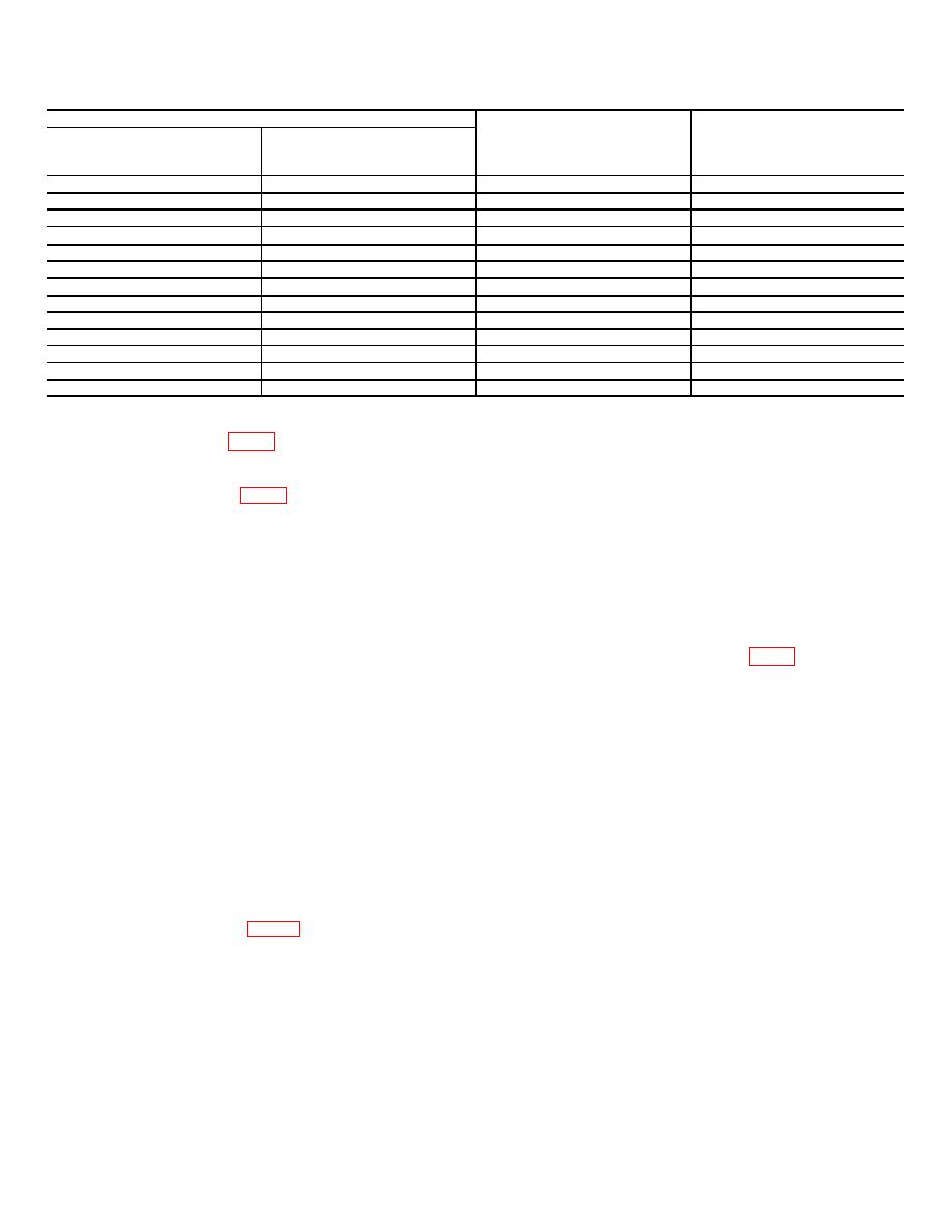
Table 5. Time-Division Accuracy - Continued
Test Instrument
TIME-DISTANCE
Time-Mark
TIME/DIV
Multiplier
Generator
Markers
setting
switch setting
setting
per/div
10 ns
X10
10 nS
1
5 ns
X10
5nS
1
2 ns
X10
2 nS
1
.1s
.1S
X1
1
50 ns
X1
50 nS
1
20 ns
X1
10 nS
2
10 ns
X1
10 nS
1
5 ns
X1
5 nS
1
2 ns
X1
2 nS
1
1 ns
X1
2 nS
.5
5 ns
X1
5 nS
1
2 ns
X1
2 nS
1
1 ns
X1
2 nS
.5
(b) TIME-DISTANCE multiplier switch to
b. Adjustments.
X.1.
(1) Adjust R525 (fig. 1) for 1 marker per division
(c) TIME/DIV switch to 5 ns.
between second and 10th graticule lines on oscilloscope
(d) TIME-DISTANCE dial to 0 (zero).
crt (R).
(e) FINE control fully clockwise.
(2) Adjust C535 (fig. 1) for 1 sine wave per
(f) DC OFFSET control to display pulse on
division between second and 10th graticule lines on
oscilloscope (A3) crt.
oscilloscope crt (R).
13. TIME-DISTANCE Dial Accuracy. a. Performance
(4) Turn delay line TRIGGER SELECTOR
Check.
control to 1 and turn trigger recognizer STABILITY
(1) Set time-mark generator (A5) to 1S
control fully clockwise; and turn LEVEL control to
midrange. If leading edge of pulse level (10 to 20
markers.
percent) is not aligned with vertical graticule centerline
(2) Position TI controls as listed in (a) through
on oscilloscope crt, perform b below.
(d) below:
(a) mV/DIV switch to 200.
to 20 percent level of leading edge of display with
(b) TIME-DISTANCE multiplier switch to
vertical graticule centerline on crt.
X10.
15. Pulse Position. a. Performance Check.
(c) TIME/DIV switch to 20 ns.
(1) Remove trigger recognizer (A6) and install
(d) TIME-DISTANCE dial to 0 (zero).
pulse generator (A4) in TI.
(3) Turn trigger recognizer (A6) controls fully
(2) Connect pulse generator to sampling head
clockwise.
(A7) LOWER INPUT, using cable (B6).
(4) Turn TI FINE control to aline leading edge of
(3) Position TI controls as listed in (a) through
marker on center vertical graticule line on oscilloscope
(e) below:
(A3) crt. Note reference point.
(a) mV/DIV switch to 100.
(5) Turn TI TIME-DISTANCE control to align
(b) TIME-DISTANCE multiplier switch to
10th marker on reference point noted in (4) above. If
X.1.
TIME-DISTANCE dial does not indicate between .90 and
1.1 s, perform b below.
(c) TIME-DIV switch to 1 ns.
(d) TIME-DISTANCE control to 0 (zero).
b. Adjustments. Turn TIME-DISTANCE control to
(e) FINE (zero set) control fully clockwise.
1.00 s and adjust R668 (fig. 2) until 10th marker is
(4) If leading edge of pulse is not aligned with
aligned with reference point noted in a(4) above (R).
vertical graticule centerline on oscilloscope (A3) crt,
14. Delay Calibrate Control. a. Performance Check.
perform b(1) below.
(1) Connect delay line (A2) output 1 to sampling
(5) Set TI TIME-DISTANCE multiplier switch to
head (A7) lower input, using cable and adapter (B4 and
X1. If pulse display is not aligned with vertical graticule
B2).
centerline, perform b(2) below.
(2) Connect delay line input 1 to trigger
(6) Depress TI HIGH RESOLUTION switch and
recognizer (A6) TRIG OUT, using cable and adapter (B5
turn SCAN control fully counterclockwise. If oscilloscope
and B2).
crt does not display 1 sweep in 50 or more seconds,
(3) Position TI controls as listed in (a) through
perform b(3) below.
(f) below:
(a) mV/DIV switch to 500.
8

