
TB 11-6625-2974-30
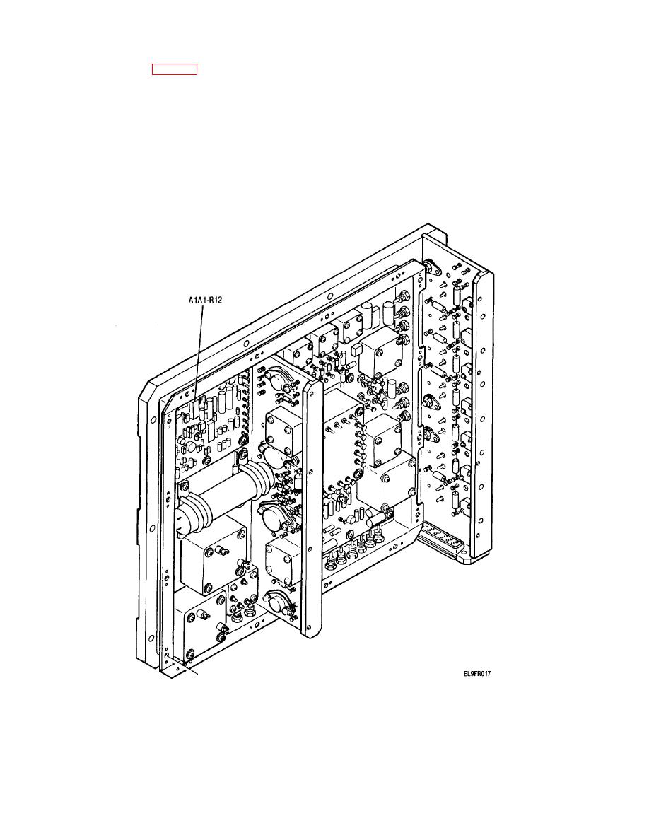
(6) Adjust AlAl-R12 (fig. 4-12) to obtain a reading of
c. +5 Vdc (B) Performance Check.
+ 5.
0.01 V on DVM.
(1) Connect DVM to +5 VDC(B) red (+) and gray (-)
(7) Set STE PRIME POWER AC and DC switches
jack.
to OFF.
(2) Observe DVM. Reading should be +5.2 0.V.
(8) Disconnect A3P9 from A1J1
If the performance standard is met,
go
to
(9) Reinstall power supply cover. Tighten 16 captive
subparagraph e (below) for the next
screws.
performance check. If not, go to subparagraph d
(10) Reinstall power supply A1(TM 11-6625- 2974-
(below) for adjustment.
13).
d. +5 Vdc (B) Adjustment. Adjust A1-R34 (fig.4-13)
(11) Set STE PRIME POWER AC and DC switches
to obtain a reading of +5.20 0.01 on DVM.
to ON.
Figure 4-12. =5V Adjustment Location.
4-15

