
TB 55-4920-431-35
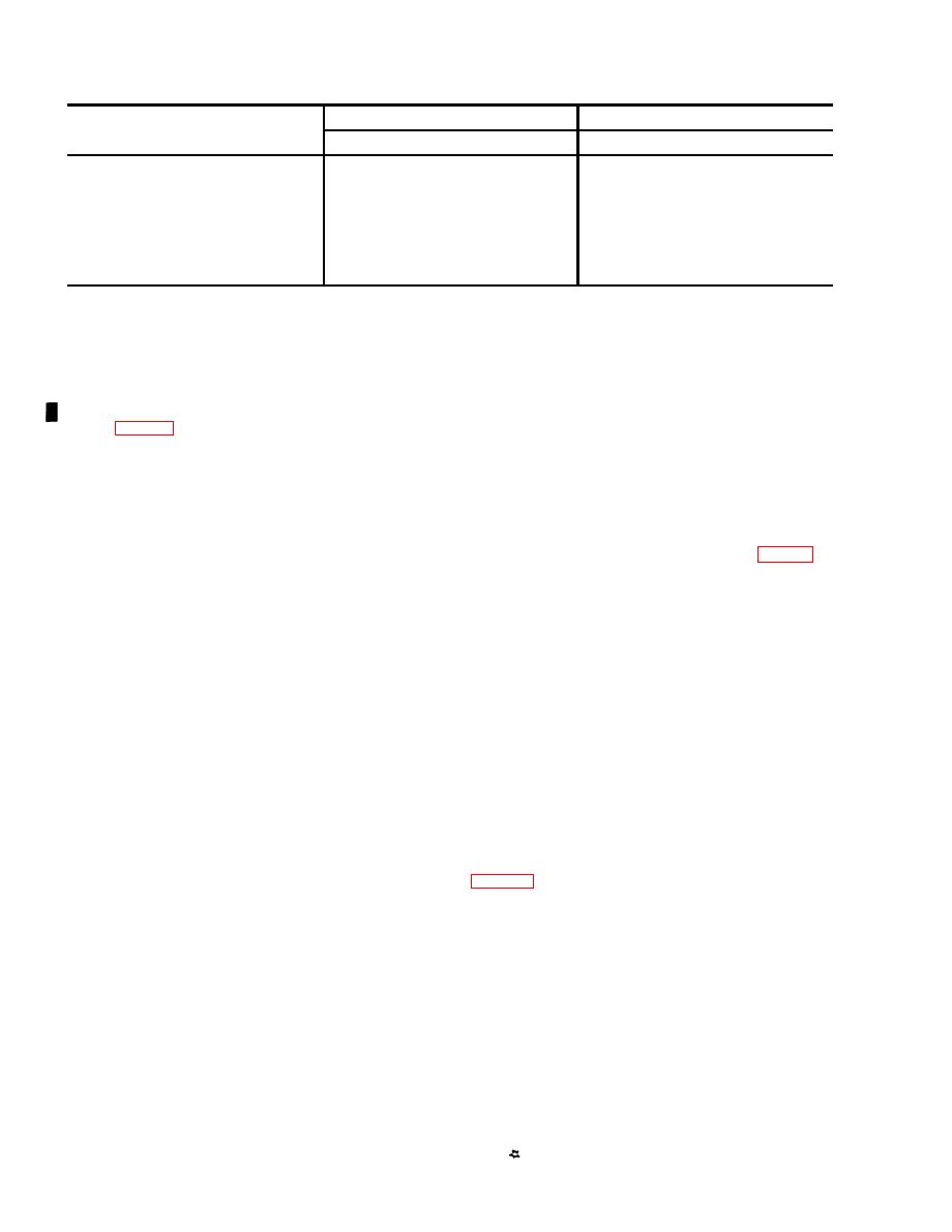
Table 5. Speed Indicator % RPM Check
Electronic Counter
Indication (Hz)
TI Speed Indicator
% RPM
Min
Max
40
1773
1960
2706
2893
60
80
3640
3826
100
4573
4759
120
5506
5693
NOTE: 1.0% rpm = 46.66 Hz
10.
Temperature Indicator.
Performance check.
a.
(1)
Connect test oscillator (A3) leads to connection B input jacks yellow and brown on adapter box
(C1) in figure 1.
(2)
Set TI Power switch to ON.
Adjust test oscillator Frequency controls for indication of 300F on Tl temperature indicator. Elec-
(3)
tronic counter (A2) will indicate between 405 and 443 Hz. If not, perform b(1) thru (4) below.
(4)
Adjust test oscillator frequency controls for each TI F temperature indications as listed in table 6.
Electronic counter will indicate within the limits specified. If not, perform b(1) thru (6) below as required.
(5)
Set TI POWER to OFF.
Disconnect leads from adapter box connection B.
(6)
Adjustments.
b.
(1)
Remove TI instrument panel from case and disconnect cable connector from FREQ/ANALOG
CONVERTER.
Remove 4 mounting screws from FREQ/ANALOG CONVERTER and pull out of case.
(2)
Remove 8 screws from back cover of FREQ/ANALOG CONVERTER and place back in case with
(3)
open side up and connect FREQ/ANALOG CONVERTER cable connector.
(4)
Adjust test oscillator for 424Hz indication on electronic counter. Adjust potentiometer R23 ZERO
adjustment on TI FREQ/ANALOG CONVERTER as shown in figure 2 for 300F indication on T1.
Change 1
8
U.S. GOVERNMENT PRINTING OFFICE: 1994 - 555-028/00365

