
TB 9-1430-201-50
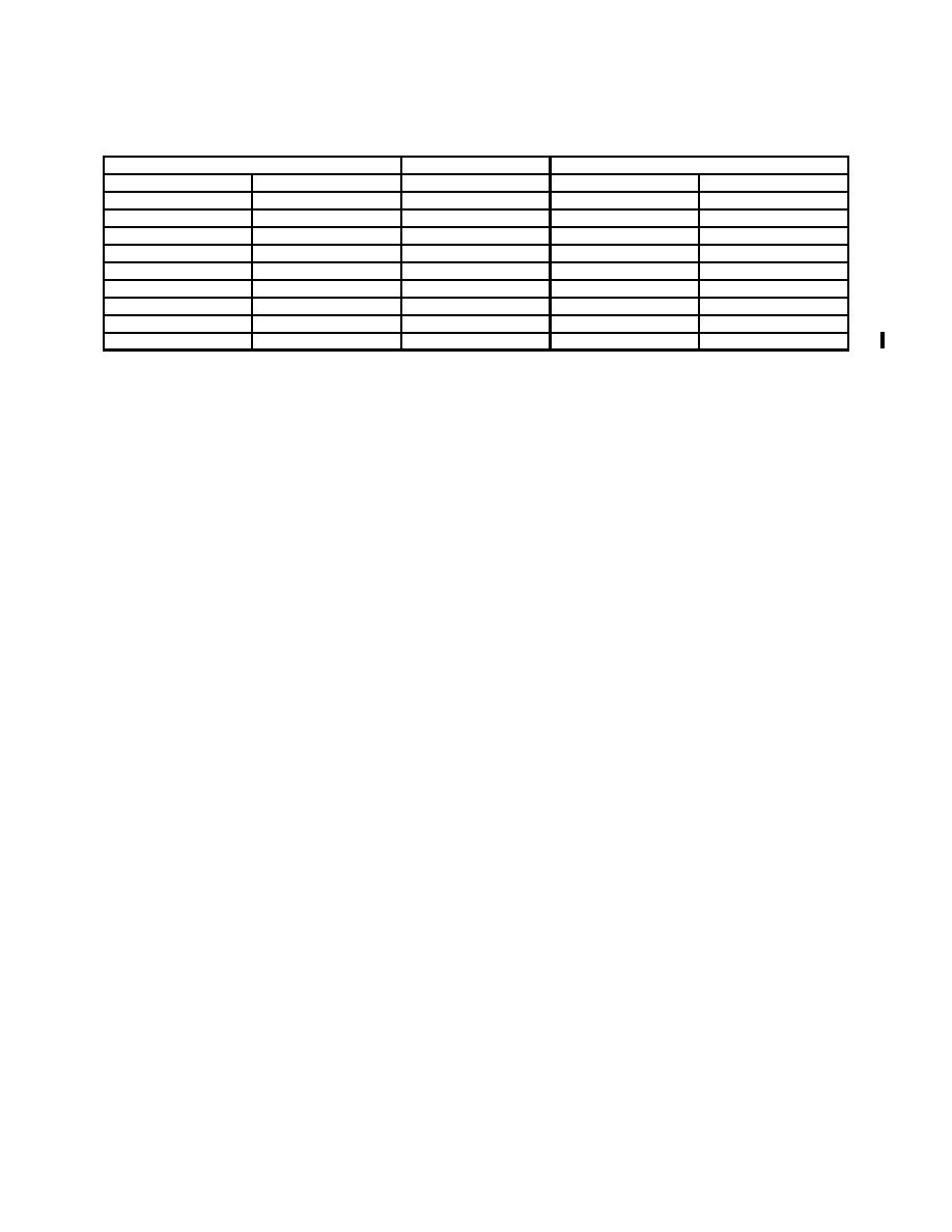
Table 5. Ratio Accuracy - Continued
Test instrument
Voltage divider
Voltage divider final indication
Outer dial setting
Inner dial setting
initial setting
Min
Max
9
0
90000
89900
90100
8
0
80000
79900
80100
7
0
70000
69900
70100
6
0
60000
59900
60100
5
0
50000
49900
50100
4
0
40000
39900
40100
3
0
30000
29900
30100
2
0
20000
19900
20100
1
0
10000
09900
10100
b. Adjustments
(1) Turn TI dials to indicate 5 on outer dial and 0 on inner dial.
(2) Adjust voltage divider to 5000000.
(3) Loosen setscrew on TI dial and remove dial assembly.
(4) Adjust TI dial shaft until null indicator indicates a null.
NOTE
It may be necessary during this adjustment to decrease null
detector sensitivity by reducing voltage standard output.
(5) Replace dial assembly so that outer dial indicates 5 and inner dial indicates 0.
(6) Repeat a(5) through (7) above.
9. Final Procedure
a. Deenergize and disconnect all equipment.
b. In accordance with TM 38-750, annotate and affix DA Label 80 (US Army
Calibration System). When the TI cannot be adjusted within tolerance, annotate and affix
DA Form 2417 (Unserviceable or Limited Use tag).
SECTION IV
ESI, MODELS DP211 AND DP311
10. Preliminary Instructions
NOTE
Unless other specified, verify the results of each test and take
corrective action whenever the test requirement is not met
before continuing with the calibration.
6

