
TB 9-4920-358-24
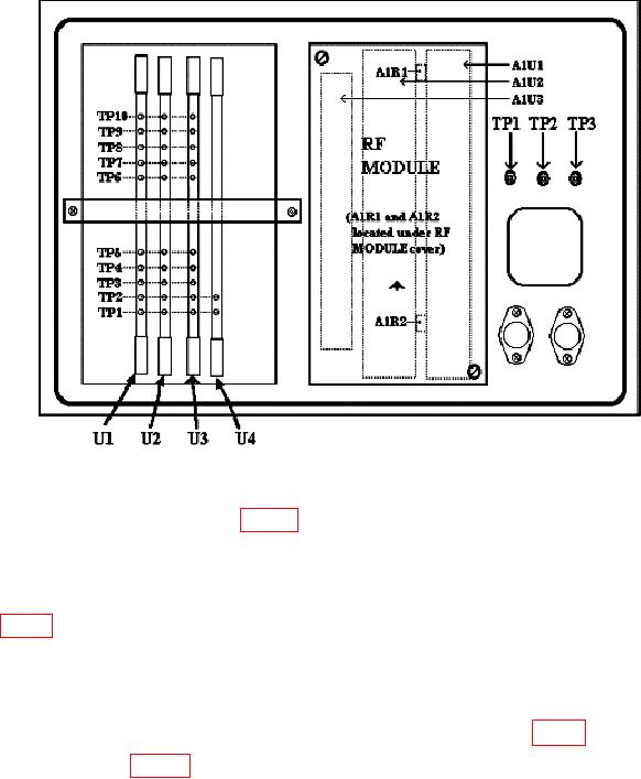
Figure 2. Test instrument rear view.
(c) Replace RF MODULE (fig. 2) into its chassis assembly and reconnect the
three RF cables.
(2) Set TI POWER switch to ON.
(3) Connect end of cable which was connected to TI RADIATED TEST ANTENNA
connector (fig. 1) to peak power meter sensor.
(4) On signal generator, set pulse modulation to off and adjust RF power level to
obtain a reading of -6 dBm on peak power meter.
(5) Set signal generator pulse modulation to on. Disconnect cable from peak power
(6) Adjust A1R1 (fig. 2) until ACCEPT/REJECT indicator just changes from
REJECT to ACCEPT (R).
9. Receiver Frequency and Bandwidth
a. Performance Check
(1) Set TI SYSTEM TYPE switch to LOBING.
(2) On signal generator increase RF output 3 dB from threshold point noted in 8 a
(4) above. Select POWER and ENTER to perform a power measurement sequence, then
press up or down arrow keys to stop the measurement.

