
TB 9-4920-358-24
(3) On signal generator increase output frequency until TI REJECT lamp comes
on. Decrease frequency until TI ACCEPT lamp just lights. Record frequency.
then increase frequency until TI ACCEPT lamp just lights. Record frequency.
(5) Subtract lower frequency recorded in (4) above from upper frequency recorded in
(4) above. Bandwidth will be between 6 and 8 MHz.
(6) Compute center frequency by adding the frequencies recorded in (4) and (5)
above and dividing by 2. Center frequency will be between 1089.5 and 1090.5 MHz.
b. Adjustments. No adjustments can be made.
10. Receiver Reference Code, Emergency and I/P Function Operation
a. Performance Check
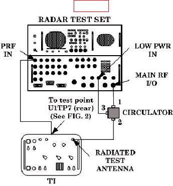
(1) Connect equipment as shown in figure 3.
Figure 3. Receiver reference code equipment setup.
(2) Set TI SYSTEM TYPE switch to SINGLE CHANNEL.
(3) Initialize radar test set by selecting FUNCTION and ENTER. Set radar test set
INTERROGATOR menus as listed below:
Menu 3 - M1 through MC REPLY CODES to 7700, RANGE DELAY to 0 s,
(a)
SIF2 to OFF.
Menu 4 - SIF CODE to 7700, DELAY to 3 s, TRIG SOURCE to EXTERN+.
(b)
(c)
Menu 14 - PRF to 257 PPS, 0 TRIG to INTERNAL.
(d)
Menu 16 - SOURCE to LOW PWR, and RF to - 0.
(4) Select radar test set Menu 16, POWER, and ENTER to perform measurement
sequence. Press up or down arrow to stop measurement.

