
TB 9-4920-358-35
(3) Measure pulse power output of TI. If measured output power is not between -5
and -7 dBm, perform b below.
RF module cover (R).
12. Transmitter Frequency
a. Performance Check
NOTE
RF module cover must be in place for the following checks.
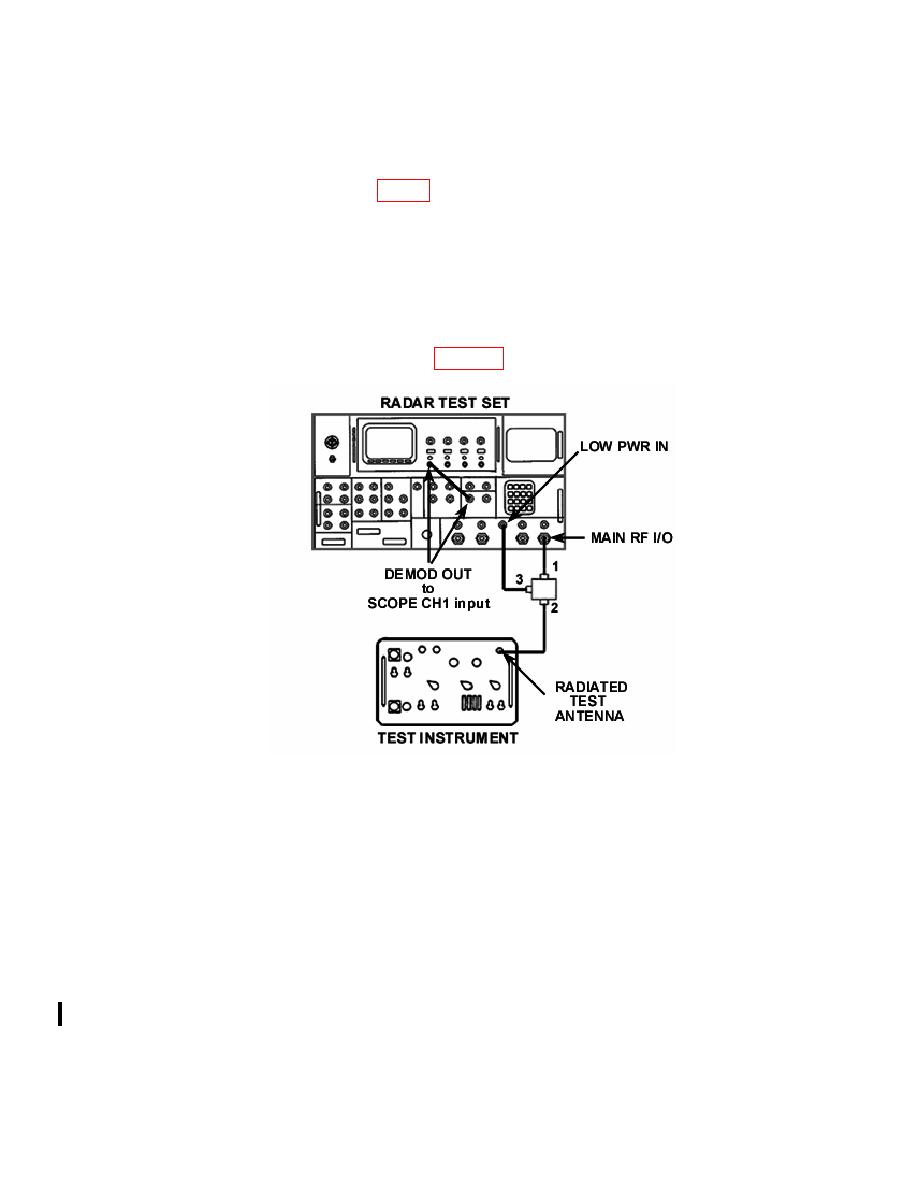
(1) Connect equipment as shown in figure 3.
(2) Set TI switches as listed in (a) through (d) below:
(a)
MODE switch to 2.
(b)
REFERENCE CODE switches to 7700.
(c)
FUNCTION switch to SYSTEM.
(d)
SYSTEM TYPE switch to SINGLE CHANNEL.
(3) Initialize radar test set by selecting FUNCTION and ENTER. Set radar test
set INTERROGATOR menus as listed below:
(a) Menu 3 - M2 to 7700, RANGE DELAY to 0 s, SIF2 to OFF.
(b) Menu 4 - SIF CODE to 7700, DELAY to 3 s, TRIG SOURCE to
EXTERN+.
(c) Menu 11 - MODULATION to OFF.
10 CHANGE 1

