
TB 9-4920-361-24
b. Adjustments. No adjustments can be made.
a. Performance Check
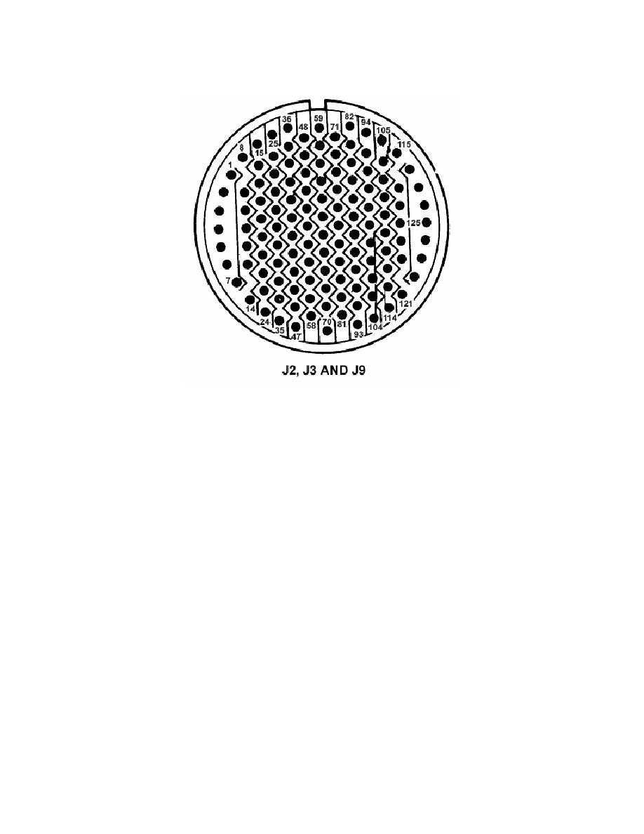
(1) Disconnect lead from J2 pin 43 and connect to J6 pin 31 on unit tester.
(2) Set ROTOR OVERSPEED 127% switch to ON.
(3) Set ON-OFF-SIM ONLY switch to ON. Multimeter will indicate between 4.5
and 5.5 V dc.
(4) Set ROTOR OVERSPEED 127% and ON-OFF-SIM ONLY switches to OFF.
(5) Disconnect lead from J6 pin 31 and connect to J6 pin 32.
(6) Repeat (2) through (4) above, except use ROTOR OVERSPEED 137% switch.
(7) Disconnect lead from J6 pin 32 and connect to J6 pin 33.
(8) Repeat (2) through (4) above, except use ROTOR OVERSPEED 142% switch.
b. Adjustments. No adjustments can be made.
a. Performance Check
(1) Disconnect lead from J6 pin 33 and connect to J2 pin 1 on unit tester.
(2) Set LOGIC P/S switch to 1.

