
TB 9-4920-451-24
20. Capacitance
a. Performance Check
(1) Connect variable capacitor, 1150 to tank unit A coax connector using shielded
test probe (p/o TI).
(2) Connect variable capacitor GND terminal to TI B-UNSH terminal using
unshielded test probe (p/o TI).
(3) Set variable capacitor for 100 pF.
(4) Set FUNCTION SELECTOR switch to TANK UNIT TEST-UNSH and set
RANGE SELECTOR switch to X1. If capacitance indicator meter does not indicate
between 99.50 and 100.50 pF, perform b below.
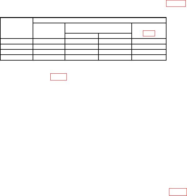
(5) Repeat (4) above using settings, indications, and adjustments listed in table 8.
Table 8 Capacitance
Test instrument
Variable
Indications
capacitor
Adjustments
(pF)
Range
(pF)
Min
Max
300
X3
99.50
100.50
C103
1000
X10
99.50
100.50
C105
1000
X50
19.50
20.50
---
50001
X50
99.50
100.50
---
1Subitute
capacitance standard.
b. Adjustments. Adjust C101 (fig. 3) for a capacitance indication of 100 pF.
21. Resistance
a. Performance Check
(1) Set RANGE SELECT switch to ZERO CAL. If megohmmeter does not indicate
zero adjust ZERO ADJ (front panel) for zero indication.
(2) Set CAP RES-CHECK switch to MEGOHMS AC position and set A-B
MEGOHMMETER and RANGE SELECTOR switch to MIDSCALE CAL position. If
megohmmeter does not indicate midscale, adjust MIDSCALE ADJ (front panel) for
midscale indication.
(3) Connect resistance standard No. 1 to TANK UNIT A and TANK UNIT B using
cables furnished with TI.
(4) Set resistance standard No. 1 for 500,000 .
(5) Set megohmmeter RANGE SELECTOR switch to X1.
(6) Adjust resistance standard No .1 for an indication of 0.5 M on megohmmeter.
Resistance standard will indicate between 450,000 and 550,000 .
(7) Repeat technique of (5) and (6) above for settings and indications listed in table 9.

