
TB 9-4920-460-24
8. Transmitter
a. Performance Check
(1) Turn the TI on by holding down the DELETE 90/30 switch while applying
power by toggling the DC switch UP to access the no modulation mode. Press ENT to
disable the modulation and allow 30 minute warm-up time.
(2) Remove antenna termination connected to the TI ANTENNA connector and
connect frequency counter.
(3) Set TI to settings listed in first line of table 3. If frequency counter does not
indicate within limits specified in first row of table 3, perform b (1) and (2) below.
(4) Repeat technique of (3) above for remaining settings listed in table 3. If
frequency counter does not indicate within limits specified in first row of table 3, perform b
(1) and (2) below.
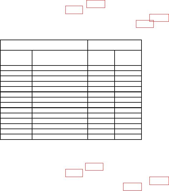
Table 3. Transmitter Frequency Accuracy.
Frequency counter
Test instrument
indication (MHz)
FUNCTION
Frequency (manually
switch
entered)
Min
Max
settings
(MHz)
LOC
108.10
108.09985
108.10015
LOC
111.95
111.94985
111.95015
VOR
108.00
107.99985
108.00015
VOR
117.95
117.94985
117.95015
1
GS
108.95
329.1497
329.1503
GS1
110.15
334.2497
334.2503
MB
75
74.99985
75.00015
29-88
29
28.99985
29.00015
29-88
59
58.99985
59.00015
29-88
88
87.99985
88.00015
156-174
174
173.99985
174.00015
225-400
225
224.9997
225.0003
225-400
312
311.9997
312.0003
225-400
400
399.9997
400.0003
ILS and GS frequencies are automatically paired.
1
(5) Connect measuring receiver to the TI ANTENNA connector and configure
measuring receiver for Tuned RF Level measurements.
(6) Set TI to settings listed in first line of table 4. If measuring receiver does not
indicate within limits specified in first row of table 4, perform b (3) through (21) below.
(7) Repeat technique of (6) above for remaining settings listed in table 4. If
measuring receiver does not indicate within limits specified in table 4, perform b (3)
through (21) below.

