
TB 9-4920-460-24
(7) Toggle and hold MB NAV ID switch to down position. ADD SDM box and Freq
1000 Hz Modulation box indication values. If calculated value is not 50% 3%, perform b
below.
(8) Release TI MB NAV ID switch to center position.
(9) Set TI ILS/VOR switch to settings listed in table 12. If AMR DDM box
indications are not within limits specified in table 12, perform b below.
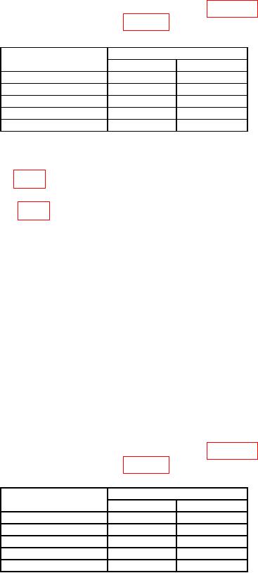
Table 12. LOC Modulation Accuracy.
AMR DDM indication limits
TI ILS/VOR switch
settings
Min
Max
D2/L2
-0.175
-0.135
D1/L1
-0.103
-0.083
OC
-0.01
0.01
U1/R1
0.083
0.103
U2/R2
0.135
0.175
b. Adjustments
(1) Adjust R41 (fig. 3) for equal amounts of modulation in AMR Freq 90 Hz and
Freq 150 boxes.
(2) Adjust R182 (fig. 3) for between 19 and 21% in AMR Freq 90 Hz and Freq 150
Hz boxes.
12. GS Modulation
a. Performance Check
(1) Set TI FUNCTION switch to GS and ILS/VOR switch to OC/0 position.
(2) Connect TI RT connector directly to measuring receiver (no sensor).
(3) Configure AMR software for Input to RF, Meas to ILS Glideslope, DUT Power to
-30 dBm, Ext. Loss to 1.00, RF Tuning to 329.150, PSA to Connect, Control to Continuous
then Start.
(4) If AMR Freq 90 Hz boxes do not indicate 90 Hz 0.9 Hz and 40% 2%, perform b
below.
(5) If AMR Freq 150 Hz boxes do not indicate 150 Hz 1.5 Hz and 40% 2%, perform
b below.
(6) If AMR SMD box does not indicate 80% 3%, perform b below.
(7) Set TI ILS/VOR switch to settings listed in table 13. If AMR DDM box
indications are not within limits specified in table 13, perform b below.
Table 13. GS Modulation Accuracy.
AMR DDM indication limits
TI ILS/VOR switch
settings
Min
Max
U2/R2
-0.195
-0.155
U1/R1
-0.101
-0.081
OC
-0.01
0.01
L1/D1
0.081
0.101
L2/D2
0.155
0.195

