
TB 9-4931-217-40
NOTE
A dash(-), in the position of a control indication, represents the
number 10 in that position.
(10) Turn MAIN DIAL to 9.9(-)00.
(11) Connect TI UNKNOWN terminals 1 and 2 to potential terminals of resistor
standard no. 1, using wire.
(12) Repeat (4) (b) and (c), and (5) through (9) above
NOTE
When nominal value of resistor being measured is 1000 ohm or
greater, subtraction of lead resistance is not required. Round
off vernier control indications to nearest multiple of 10.
NOTE
Minimum and maximum values listed are applicable when test
report values equal nominal values. If test report value is
different from nominal value, this difference must be combined
with values recorded in (9) and (12) above.
(13) Subtract value recorded in (9) above from value recorded in (12) above.
Resistance value obtained will be within limits specified in table 5.
(14) Repeat technique of (11) through (13) above, using resistors, switch settings,
and indications listed in table 5.
NOTE
Set dc generator detector GENERATOR RANGE switch to a
setting that corresponds to 10 times nominal value of resistor
connected to UNKNOWN.
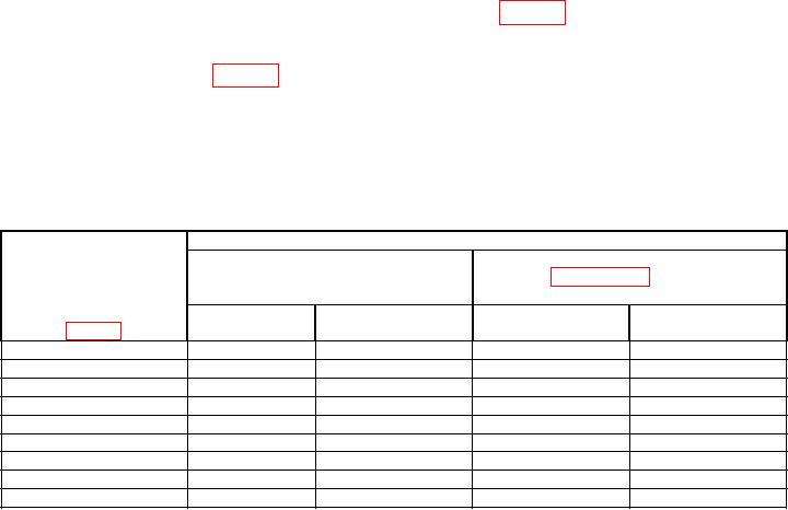
Table 5. Range Switch Accuracy
Test instrument
Resistor connected
Resistance value obtained in
RANGE
to UNKNOWN
paragraph 18 a above
( )
terminals
Switch
common name
Nominal
Position
( )
value
Min
Max
-4 k
Resistor Standard No. 1
1
10
0.9990
1.0010
10-3 k
Resistor Standard No. 2
10
9.9950
10.0050
2k
Resistor Standard No. 3
100
10-
99.950
100.050
1k
Resistor Standard No. 4
1k
10-
999.5
1000.5
2
Resistor Standard No. 4
1k
1k
999.5
1000.5
1
Resistor Standard No. 5
10 k
1k
9.995 k
10.005 k
10 k2
Resistor Standard No. 5
10 k
9.995 k
10.005 k
1
Resistor Standard No. 6
100 k
10 k
99.95 k
100.05 k
2
Resistor Standard No. 6
100 k
100 k
99.9 k
100.1 k
1Use
an initial MAIN DIAL setting of either 9.9(-)00 or 9.9900 when obtaining resistance value on this RANGE position.
2Repeat
(14) above, using an initial MAIN DIAL setting of either 0.9(-)00 or 0.9900.
17

