
TB 9-4931-363-50
(8) Connect the ac voltage calibrator to METER JACKS J16 and J17 with test
leads. Energize the ac calibrator.
(9) Set the ac calibrator and the digital multimeter controls to the settings given in
the ac calibrator within the tolerance specified. If the indication is within tolerance,
proceed to (11).
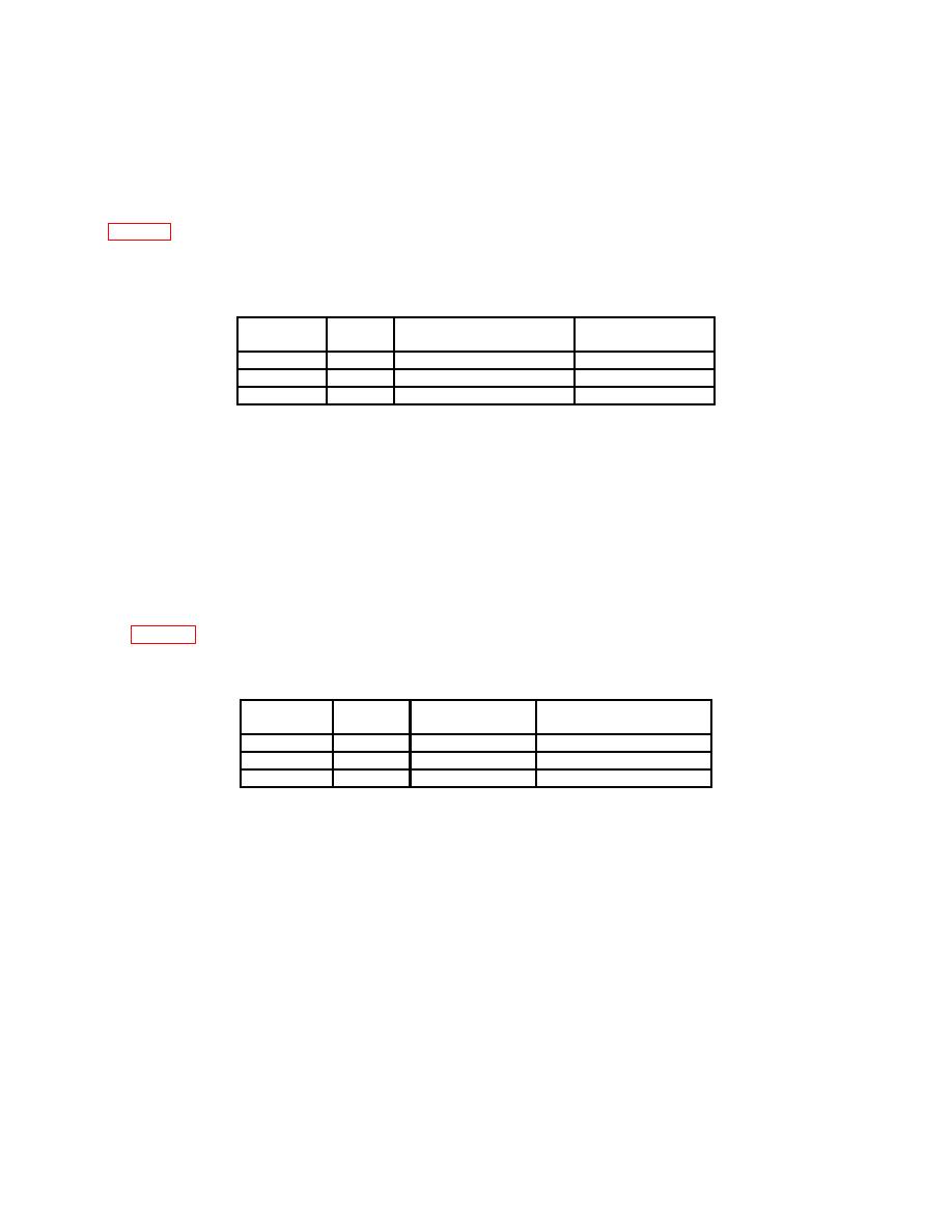
Table 5. AC Performance Check
Function
Range
Test
Multimeter
Select
Select
Input
Reading
ACV
1
1.000 VDC 400 Hz
0.995 to 1.005
ACV
10
10.00 VDC 400 Hz
9.95 to 10.05
ACV
100
100.0 VDC 400 H7
99.5 to 100.5
(10) If any digital multimeter reading is out of tolerance, perform adjustment as
indicated in b below.
(11) Deenergize and disconnect the ac calibrator.
(12) Deenergize the test set and disconnect it from the power source.
(13) Connect the decade resistor to METER JACKS J16 and J17 with test leads.
(14) Set the decade resistor and the digital multimeter controls to the settings given
in table 6. For each setting, check that the digital multimeter reading is the same as that
of the decade resistor within the tolerance specified.
Table 6. Resistance Performance Check
Function
Range
Test
Multimeter
Select
Select
Input
Reading
1
1.000K
0.95K to 1.05K
KΩ
10
1 0.00K
9.5K to 10.5K
100
100.0K
95.0K to 105.0K
(15) If the digital multimeter reading is out of tolerance, return the multimeter to the
manufacturer's facility for repair.
b. Adjustment
(1) Remove the test set chassis assembly from the test set container.
(2) Remove the power supply mounting plate by removing 10 screws. Lay the plate
adjacent to the test set chassis assembly without putting strain on the wiring.
(3) Remove the rear cover of the digital multimeter by removing one screw in the
center of the cover. Adjustments are located in the lower left-hand corner. Reference
designations for the adjustments are stamped on the adjacent panel.
6

