
TB 9-4931-405-40
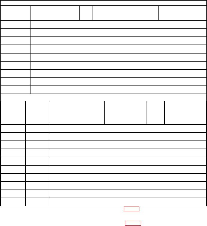
Table 3. Guildline, Model 9711 Calculations Worksheet
Section A
Nominal
Actual calibrator
calibrator
Multimeter indication
Standard resistor
output
output
(in V)
test report value
(No.)
(in A)
_____________________
A
_____________________
(6) =
_____________________
10
_____________________
A
_____________________
(5) =
_____________________
100
_____________________
1.0
mA
_____________________
(4) =
_____________________
_____________________
10.0
mA
_____________________
(3) =
_____________________
_____________________
100
mA
_____________________
(2) =
_____________________
_____________________
1.0
A
_____________________
(7) =
_____________________
_____________________
2.0
A
_____________________
(8) =
_____________________
_____________________
A1
10
_____________________
(8) =
_____________________
_____________________
A2
20
_____________________
(9) =
_____________________
Section B
Test
instrument
Test instrument
Nominal
plug
calculated
calibrator
Multimeter indication
Actual calibrator
position
resistance value
output
output3
(in V)
__________________
A
.00001
__________________
=
__________________
10
__________________
A
.0001
__________________
=
__________________
100
__________________
.001
1.0 mA
__________________
=
__________________
__________________
.01
10.0 mA
__________________
=
__________________
__________________
.1
100
mA
__________________
=
__________________
__________________
1
1.0 A
__________________
=
__________________
__________________
10
2.0 A
__________________
=
__________________
__________________
A4
10
10
__________________
=
__________________
__________________
A2,5
100
20
__________________
=
__________________
__________________
A2,6
300
20
__________________
=
__________________
1Set
calibrator output to minimum; then connect test lead as shown in figure 1, CONNECTION B.
2Substitute
DC power supply for calibrator.
3Transcribe
recorded values from section A to section B.
4Set
calibrator output to minimum; then connect test leads as shown in figure 2, CONNECTION B.
5Set calibrator output to minimum; then move test lead from TI's 10 AMP terminal to 100 AMP terminal.
6Set DC power supply output to minimum; then move test lead from TI's 100 AMP terminal to 300 AMP terminal. Allow
20 minutes to warm-up.
7

