
TB 9-4931-444-35
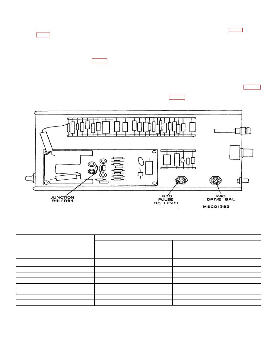
(6) Connect dc voltmeter (.A2) to TI junction
{2) .Adjust PULSE DC LEVEL R30 (fig. 2) until dc
R41/R54 (fig. 2) and chassis ground. using probe (B7).
voltmeter indicates between 66.00 and 69.00 volts.
If dc voltmeter does not indicate between 66.00 and
(3) Due to interaction of adjustments, repeat (1) and
69.00 volts, perform b(2) and (3) below.
(2) abode for optimum results.
(7) Remove probe connected in (6) above.
b. Adjustments
10. Pulse Repetition Rate
(1) Adjust DRIVE BAL R40 (fig. 2) and both
POSITION controls until CHI and CH2 signals are
a. Performance check
superimposed.
(1) Turn
TI
AMPLITUDE
control
fully
counterclockwise.
NOTE
(2) Position TI REPETITION RATE switch and
If adjustment R40 does not superimpose
oscilloscope (A3) TIME/CM switch as listed in table 4.
signals, adjust oscilloscope POSITION
Oscilloscope will display waveforms within limits
controls to display separate waveforms
specified in table 4.
and then adjust for equal amplitudes.
Figure 2. Calibration adapter - left side view.
Table 4. Repetition Rates
Test Instrument
Oscilloscope
REPETITION RATE
Cycles Per 10
Switch Settings
TIME/CM
Centimeters
Switch Settings
Display
1
1 ms
7.5 to 12.5
1 kHz
4 kHz
.2 ms
.2 ms 6to 10
50s
15kHz
5.6to9.4
10 s
80 kHz
6to 10
2s
500 kHz
7.5to 12.5
2
3
LOW
.2 ms
.2 ms 7.5 to 12.5
10 s
2
4
MED
9 to 154
2s
2
HIGH
9to 15
1
For types with S/N 3995 and above.
2
For types with S/N 3995 and below.
3
Display will be form 8 to 12 cycles for types with S/N 1409 and below.
4
Display will be from 8 to 12 cycles for types with S/N between 1409 and 3995.
6

