
TB 9-4931-488-24
(c) Connect BNC T connector to 600 Ω feed through.
(d) Connect 600 Ω feed through to AM OUTPUT.
(3) Set TI SCALE to LEVEL VOLTS. Set ANALYZER to measure LEVEL.
(4) Adjust OUTPUT LEVEL for a TI meter indication as listed in table 18. Voltage
should read > 1 V rms ( > 3 V rms for option 001) on audio analyzer. Adjust TI to the first
settings as listed in table 18. Set ANALYZER to measure DIST.
(5) Audio analyzer and frequency counter should indicate within limits specified in
(6) Set TI to the remaining functions and settings listed in table 18 and repeat
technique (5) above.
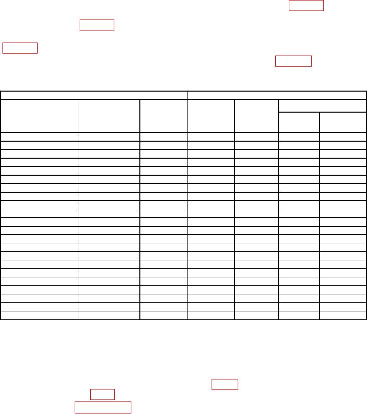
Table 18. Internal Modulation Oscillator Frequency Accuracy and Distortion.
Test instrument
Audio analyzer and frequency counter
Modulation frequency
Modulation
Audio
Distortion
Frequency (kHz)
range
frequency
output level
indication
Function
Min
Max
switch settings
vernier
volts
≤
indication
1 (3)1
FIXED FREQ 1 kHz
----------
----------
----------
----------
----------
FIXED FREQ 1 kHz
----------
----------
Frequency
----------
980 (970)
1020 (1030)
FIXED FREQ 1 kHz
----------
----------
Distortion
0.5%
----------
----------
FIXED FREQ 400 Hz
----------
----------
Frequency
----------
392 (388)
408 (412)
FIXED FREQ 400 Hz
----------
----------
Distortion
0.5%
----------
----------
2
X1
100
----------
Frequency
----------
85
115
X1
100
----------
Distortion
0.5%
----------
----------
X1
20
----------
Frequency
----------
17
23
X1
20
----------
Distortion
0.5%
----------
----------
X10
100
----------
Frequency
----------
850
1150
X10
100
----------
Distortion
0.5%
----------
----------
X10
200
----------
Frequency
----------
1700
2300
X10
200
----------
Distortion
1.0%
----------
----------
X100
200
----------
Frequency
----------
17,000
23,000
X100
200
----------
Distortion
1.0%
----------
----------
X100
100
----------
Frequency
----------
8,500
11,500
X100
100
----------
Distortion
1.0%
----------
----------
X1K
100
----------
Frequency
----------
85,000
115,000
X1K
100
----------
Distortion
1.0%
----------
----------
X1K
200
----------
Frequency
----------
170,000
230,000
X3K
200
----------
Frequency
----------
510,000
690,000
X3K
20
----------
Frequency
----------
51,000
69,000
Values in parentheses are for option 001.
1
Perform remaining tests only for TI's containing option 001 & H66.
2
(7)
Set RF OFF/ON switch to OFF and disconnect equipment setup.
b. Adjustments. For TI's containing options 001 & H66, perform technique of (3)
through (19) below. For all other TI's, perform (1) and (2) below.
(1) Connect true rms voltmeter to A11TP3 (fig. 3) and chassis ground.
Adjust
A11R6 (OSC LEVEL, fig. 3) for true rms voltmeter indication of 0.840 0.010 V ac.
(2) Repeat paragraph 14 a (3) through (5) above.
24

