
TB 9-4931-488-35
Options
Start
Stop
Min
Max
frequency
frequency
indication
indication
(Hz)
(Hz)
(dB)
(dB)
Standard model 001, H66
16 M
512 M
+7.5
+8.5
003
16 M
512 M
+6.75
+8.75
002
16 M
64 M
+7.25
+8.25
002
64 M
512 M
+7.0
+9.0
002
512 M
1000 M
+6.5
+9.5
002 with 003
16 M
512 M
+6.0
+9.0
002 with 003
512 M
1000 M
+6.0
+10.0
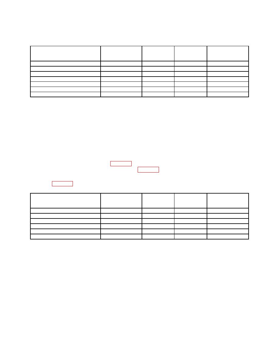
NOTE
Perform (7) through 10 below for models containing
opt 004 only. All other models proceed to (11) below.
(7) Set RANGE MHz switch to 256-128 and adjust FREQUENCY TUNE control
for a 190 MHz indication on FREQUENCY MHz display.
(8) Set RF OFF/ON switch to ON and adjust OUTPUT LEVEL 1 dB switch and
vernier control for a +8.0 dBm indication on measuring receiver.
(9) While observing measuring receiver indication, slowly vary TI frequency from
start to stop frequencies listed in table 17. Measuring receiver will indicate between
minimum and maximum indications listed in table 17.
(10) Repeat technique of (7) through (9) above for remaining options and settings
listed in table 17.
Options
Start
Stop
Min
Max
frequency
frequency
indication
indication
(Hz)
(Hz)
(dB)
(dB)
004
16 M
108 M
+7.25
+8.75
004
108 M
336 M
+7.5
+8.5
004
336 M
512 M
+7.25
+8.75
004 with 003
16 M
108 M
+6.75
+9.25
004 with 003
108 M
336 M
+7.5
+8.5
004 with 003
336 M
512 M
+6.75
+9.25
(11) Disconnect measuring receiver from TI.
b. Adjustments. No adjustments can be made.
Distortion
a. Performance Check
(1) Position controls as listed in (a) through (f) below.

