
TB 9-4931-488-35
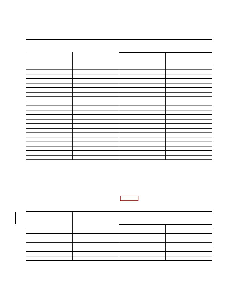
Table 29. FM Sensitivity
Measuring receiver
Test Instrument
indications
(kHz)
FREQUENCY MHz
PEAK DEVIATION
display
switch settings
Min
Max
64
320
301
339
64
160
150
170
64
80
75.2
84.8
64
40
37.6
42.4
64
20
18.8
21.2
64
10
9.40
10.6
64
5
4.70
5.30
90
320
301
339
90
160
150
170
90
80
75.2
84.8
90
40
37.6
42.4
90
20
18.8
21.2
90
10
9.40
10.6
90
5
4.70
5.30
128
320
301
339
128
160
150
170
128
80
75.2
84.8
128
40
37.6
42.4
128
20
18.8
21.2
128
10
9.40
10.6
128
5
4.70
5.30
(8) Set RANGE MHz switch to 512-256 and adjust FREQUENCY TUNE for TI
display indication of 512 MHz.
(9) Set measuring receiver for FM measurement in the automatic operation mode
with peak + detector.
(10) Set PEAK DEVIATION switch to settings and adjust audio analyzer output
level controls for TI meter indications listed in table 30. If measuring receiver does not
indicate as specified, perform b below.
Table 30. FM Accuracy
Measuring receiver indications
Test instrument
Test instrument
PEAK DEVIATION
(KHz)
meter
1
switch settings
indications
Min
Max
5
5
4.58
5.43
10
10
9.15
10.8
20
20
18.1
21.9
40
40
36.5
43.5
80
80
72.9
87.1
160
160
144
176
320
320
293
347
1Use
scale reference that is lit up under SCALE to left of TI meter.
40 CHANGE 2
PIN 063108-002

