
TB 9-4931-488-35
(c) FM control fully cw.
(d) FREQUENCY TUNE control for FREQUENCY MHz display indication of
50 MHz.
(13) Set audio analyzer for a 1 kHz 1.414 V ac output level.
(14) Repeat (8) above.
(15) Adjust MID R3 (fig. 3) for a 80.0 0.1 kHz measuring receiver indication (R).
(16) Adjust FREQUENCY TUNE control for FREQUENCY MHz display indication
of 32 MHz. Adjust LOW R2 (fig. 3) for a 80.0 0.1-kHz measuring receiver indication (R).
(17) Adjust FREQUENCY TUNE control for FREQUENCY MHz display indication
of 64 MHz. Adjust HIGH R4 (fig. 3) for a 80.0 0.1 kHz measuring receiver indication (R).
(18) Adjust FREQUENCY TUNE control for FREQUENCY MHz display indication
of 50 MHz and repeat (15) through (17) above until measuring receiver indication is 80.0
0.2 kHz at 32, 50, and 64 MHz.
(19) Set FM and RF OFF/ON switches to OFF and repeat a above.
19. Power Supply
a. Performance Check
(1) Remove top cover from TI.
(2) Check to see that the five LED's on supply boards (fig. 2) are on.
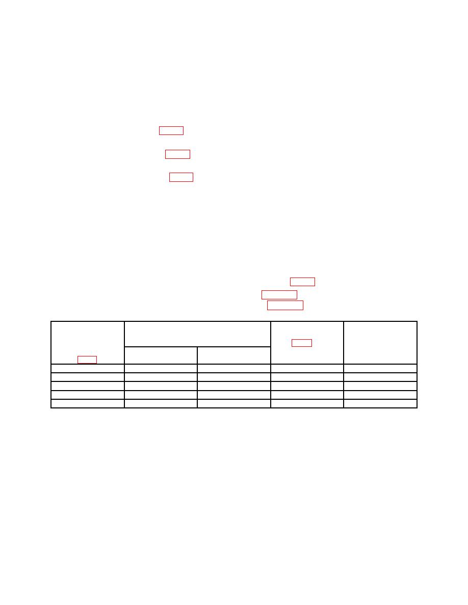
(3) Connect multimeter to test points listed in table 32 and chassis ground. If
multimeter does not indicate within limits specified in table 32, perform adjustments listed.
Test
Dc voltage limits
Adjustments
instrument
locations
indications
test point
(fig. 2) (R)
locations
Min
Max
(V Dc)
A18TP31
-5.10
-5.30
A18R12
-5.2
A20TP10
+5.10
+5.30
A20R16
+5.2
A22TP4
+19.90
+20.10
A22R7
+20
A22TP9
-19.90
-20.10
A22R19
-20
A20TP4
+44.50
+44.70
A20R8
+44.6
1For
some models, this may be TP5.
2For
some models, this may be A18R2.
20. Final Procedure
a. Deenergize and disconnect all equipment.
b. Annotate and affix DA label/form in accordance with TB 750-25.
43/(44 Blank)

