
TB 9-4931-495-24
(f) TIME-SECONDS vernier control fully cw.
(g) RF BLANKING-OFF switch (rear panel) to RF BLANKING.
(h) TRIGGER switch to INT.
(i) ALC switch to INT.
(j) RF switch to ON.
(k) 1 kHz SW WV/OFF switch (rear panel) to OFF.
(l) FM-NORM-PL switch (rear panel) to NORM.
(3) Press CW pushbutton and adjust POWER LEVEL and SLOPE controls for
maximum leveled power output.
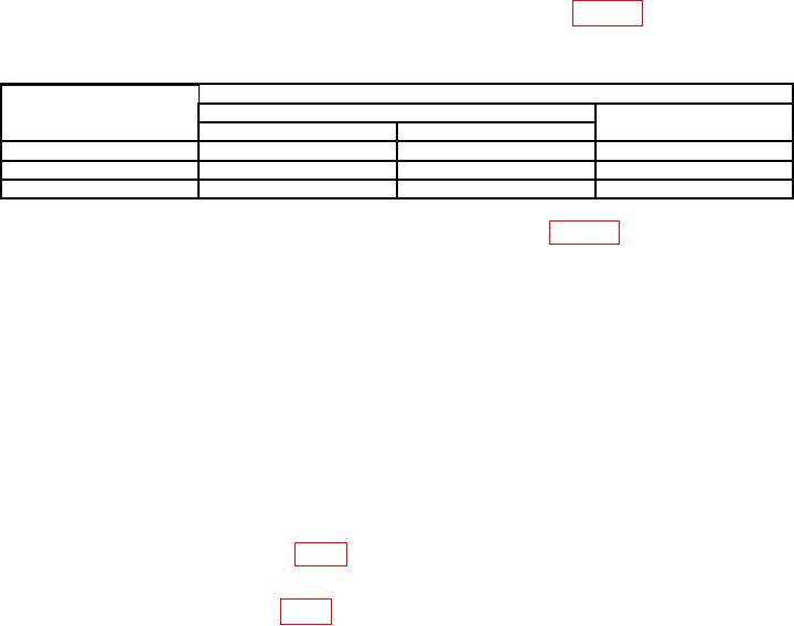
(4) Adjust POWER LEVEL control to settings listed in table 3. if output power
does not indicate within limits specified, perform b below.
Table 3. Power Output (Model 86222A)
Test Instrument
Output power
POWER LEVEL
Power level (dB)
Power variation
a(5) (dB)
settings
Min
Max
0
-1
+1
0.25
9
8
10
0.25
13
12
14
0.25
(5) At each POWER LEVEL control setting listed in table 3, slowly rotate CW
control through entire range. If output power variation does not indicate within limits
specified, perform b below.
(6) Adjust POWER LEVEL control fully cw.
(7) Slowly rotate CW control through entire range. If minimum output power
point is not greater than +13 dB, perform b below. Record minimum output power point.
(8) Adjust CW control to minimum output power point recorded in (7) above.
(9) Adjust POWER LEVEL control fully ccw. Record output power.
(10) Output power recorded in (9) above be at least 13 dB down output power
recorded in (7) above.
b. Adjustments
(1) Adjust POWER LEVEL control to +13.
(2) Adjust A3R22 H PWR (fig. 4) for output power of 13 dB (R).
(3) Adjust POWER LEVEL control to 0.
(4) Adjust A3R1 L PWR (fig. 4) for output power of 0 dB (R).
(5) Repeat a (4) through (10) and (1) through (4) above for best in-tolerance reading.
15

