
TB 9-4931-495-24
(a) MODE switch to AUTO.
(b) ALC switch to EXT.
(c) RF switch to ON.
NOTE
Insure that polarity switch inside plug-in matches crystal
detector being used when using external leveling mode.
(3) Press CW pushbutton and adjust POWER LEVEL control (and SLOPE and/or
GAIN on some models) for maximum leveled power out. If power meter does not indicate
within the limits specified in table 11, perform (b) below.
NOTE
Tolerances do not include losses due to frequency response of
thermistor mount or other accessories.
(4) Slowly rotate CW MARKER control throughout frequency range while
observing power meter indication. Power level will not vary more than limits specified in
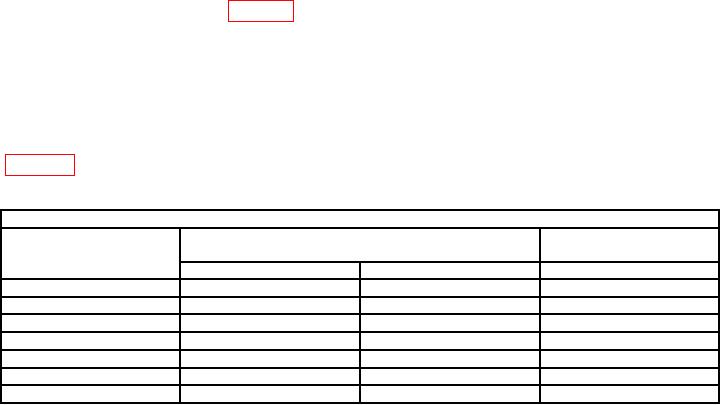
Table 11. Power Output (Models 86200 Series)
Test instrument
Variations2
Power output indications
(dBm)1
across band (dB)
Model
Min
Max
0.35
86210A
+12.65
+13.35
0.5
86220A-H80
+9
+11
1.2
86230B-H80
> +10.0
---
0.7
86241A-H80
> +4.0
---
1.0
86242A-H80
> +10.0
---
1.0
86250B-H80
> +8.0
---
0.6
86260A-H80
> +7.0
---
1Values
include power meter indication plus 10 dB attenuator (fixed) and power splitter value.
2Tolerance
does not include variations due to thermistor mount and power splitter frequency response.
(5) Connect power meter to RF OUTPUT, using attenuator (fixed).
(6) Set ALC switch to INT.
(7) Repeat technique of (3) and (4) above for models with internal leveling option.
NOTE
Steps (8) and (9) below are applicable to models with output
attenuator (fixed) (option 002).
(8) Connect power meter to RF OUTPUT, and set output attenuator (fixed) to 0
dBm. Adjust POWER LEVEL control for a convenient reference on power meter (2 dB less
than full scale).
26

