
TB 9-4931-503-24
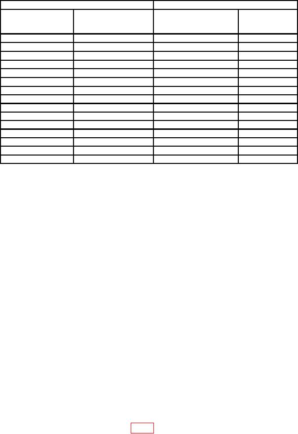
Table 7. Delayed Sweep Timing (Mag) - Continued
Test instrument
Oscilloscope calibrator
err display
MAIN SEC/DIV
DLY'D SEC/DIV
MARKER
indications
switch settings
switch settings
output settings
( %)
s
s
S/D
4
1
1
1
s
s
S/D
4
2
2
2
s
s
S/D
4
5
5
5
s
s
S/D
4
10
10
10
s
s
S/D
4
20
20
20
s
s
S/D
4
50
50
50
0.1
ms
0.1
ms
0.1
mS/D
4
0.2
ms
0.2
ms
0.2
mS/D
4
0.5
ms
0.5
ms
0.5
mS/D
4
1
ms
1
ms
1
mS/D
4
2
ms
2
ms
2
mS/D
4
5
ms
5
ms
5
mS/D
4
10
ms
10
ms
10
mS/D
4
20
ms
20
ms
20
mS/D
5
50
ms
50
ms
50
mS/D
5
(12) Position TI controls as listed in (a) through (d) below:
SWP MAG pushbutton released (out).
(a)
DLY'D SEC/DIV switch to 10 .
(b)
MAIN SEC/DIV switch to .1 m.
(c)
DISPLAY MODE INTENS SWP pushbutton pressed.
(d)
(13) Set oscilloscope calibrator MARKER output for 0.1 mS/D.
(14) Adjust MAIN TRIG LEVEL control for a stable display on oscilloscope.
(15) Adjust oscilloscope INTENSITY control until intensified portion of trace is
clearly visible.
(16) Adjust POSITION control to start trace at extreme left graticule line of display.
(17) Adjust DELAY TIME MULT dial to position start of intensified portion of trace
on 2d vertical graticule line. If DELAY TIME MULT dial does not indicate between 0.97
and 1.03, perform b (3) through (6) below.
(18) Adjust DELAY TIME MULT dial to position start of intensified portion of trace
on 10th vertical graticule line. If DELAY TIME MULT dial does not indicate between 8.89
and 9.11, perform b (3) through (6) below.
b. Adjustments
(1) Set TI MAIN SEC/DIV switch to 1 , DLY'D SEC/DIV switch to .5
and
oscilloscope calibrator MARKER output for 0.5 S/D. If necessary, adjust oscilloscope
calibrator EDIT FIELD knob for a 0.0% err display indication.
(2) Adjust TI POSITION control to align 1st time marker with 1st vertical graticule
line (extreme left). Adjust C615 HF TIM (fig. 2) to align one time marker per division (R).
12

