
TB 9-4931-503-24
(6) Press MODE CH 2 and TRIGGER CH 2 pushbuttons.
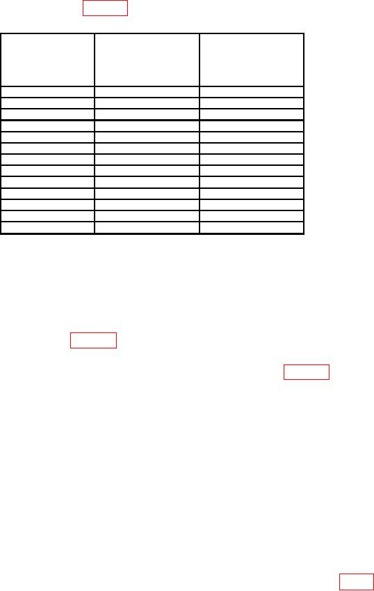
(7) Set TI CH 2 VOLTS/DIV switch and oscilloscope calibrator VOLTAGE output,
at 1 kHz, as listed in first row of table 11.
Table 11. CH 2 Vertical Gain
Oscilloscope
Oscilloscope
Test instrument
calibrator
CH 2
calibrator
err display
VOLTAGE output
VOLTS/DIV
indications
at 1 kHz settings
switch settings
( %)
1
mV
5
mV
5
2
mV
10
mV
5
5
mV
25
mV
3
10
mV
50
mV
3
20
mV
.1
V
3
50
mV
.25
V
3
.1
V
.5
V
3
.2
V
1
V
3
.5
V
2.5
V
3
1
V
5
V
3
2
V
10
V
3
5
V
25
V
3
10
V
50
V
3
NOTE
If necessary, adjust delaying time base controls for a stable
display.
(8) Adjust oscilloscope calibrator EDIT FIELD knob for 5 divisions of vertical
deflection on oscilloscope. If oscilloscope calibrator err display indication is not within
limits specified in first row of table 11, perform b (17) through (32) below. (No adjustment
can be made on TIs with main board (SN B056205 and below)).
(9) Repeat technique of (7) and (8) above for remaining rows in table 11.
b. Adjustments
(1) Connect oscilloscope calibrator SOURCH/MEASURE CHAN 1 to TI CH 1
using 24 pF normalizer.
(2) Set TI CH 1 VOLTS/DIV switch to 20 m and press CH 2 GND pushbutton to
in position.
(3) Set delaying time base MAIN SEC/DIV switch to 1 m.
NOTE
Adjust TI and delaying time base controls as necessary to view
(4) Set oscilloscope calibrator EDGE output for 100 mV, 1 kHz and adjust EDIT
FIELD knob for 5 divisions of vertical deflection on oscilloscope.
(5) If square wave level, roll off, or overshoot exceeds 4%, adjust C134 (fig. 4) for
flat top on waveform.
20

