
TB 9-4931-504-50
(4) Press CH1 and release CH2 pushbuttons.
(5) Repeat technique of (3) above for channel 1.
wave display.
23. Power Supply
NOTE
Do not perform power supply, check if all other parameters
are within tolerance.
a. Performance
(1) Connect digital voltmeter (A2) to +30 V test point (fig. 1) and chassis ground,
using leads supplied with digital voltmeter. Digital voltmeter will indicate between
+29.1 and +30.9 V dc.
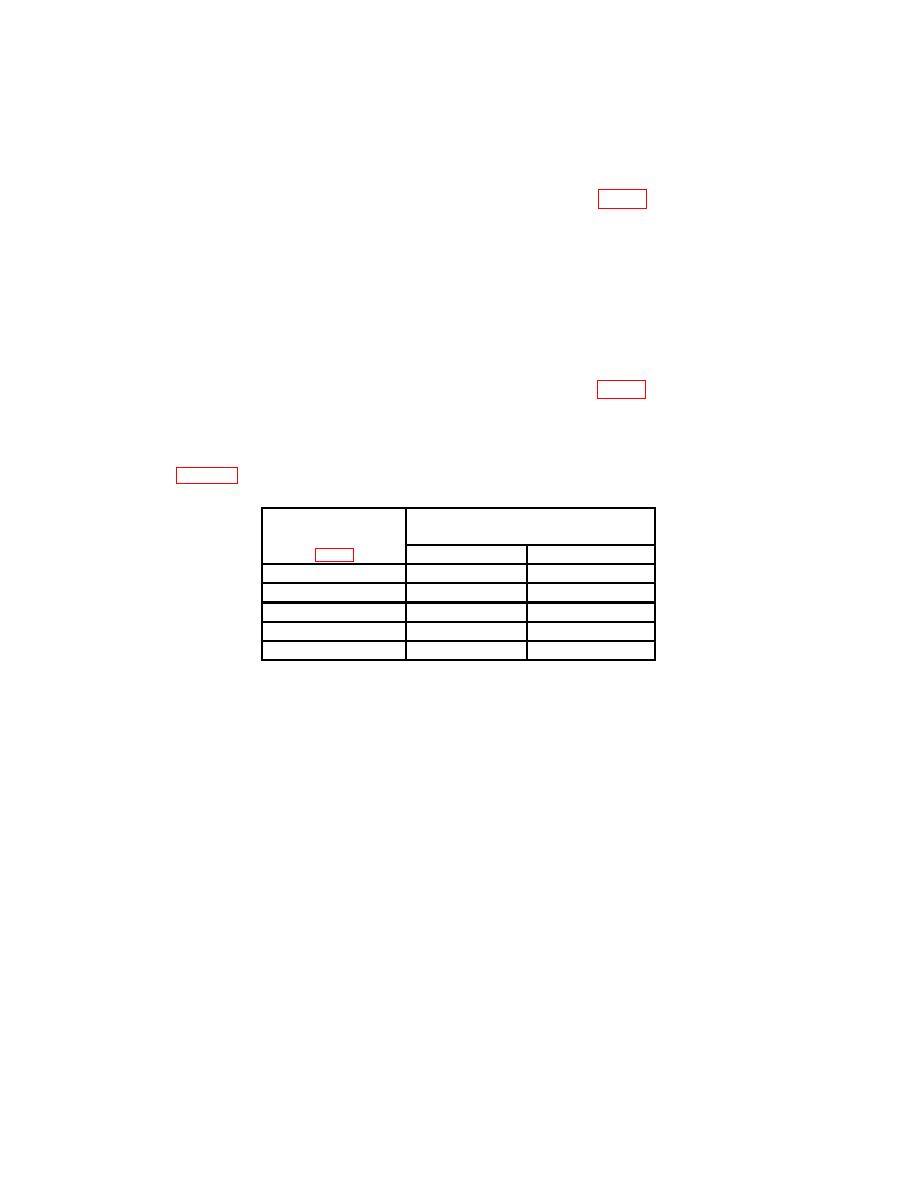
(2) Repeat technique of (1) above for test points and digital voltmeter indications
listed in table 5. Digital voltmeter will indicate within limits specified.
Test instrument
Digital voltmeter indications
test points
(V dc)
Min
Max
+15
+14.55
+15.45
-30
-29.10
-30.90
-15
-14.55
-15.45
-5
-4.85
-5.15
+5
+4.85
+5.15
b. Adjustments. No adjustments can be made.
24. Final Procedure
a. Deenergize and disconnect equipment and replace TI side panels.
b. In accordance with TM 38-750, annotate and affix DA Label 80 (US Army
Calibrated Instrument). When the TI receives limited or special calibration, annotate
and affix DA Label 163 (US Army Limited or Special Calibration). When the TI cannot
be adjusted within tolerance, annotate and affix DA Form 2417 (US Army Calibration
System Rejected Instrument).

