
TB 9-4931-537-24
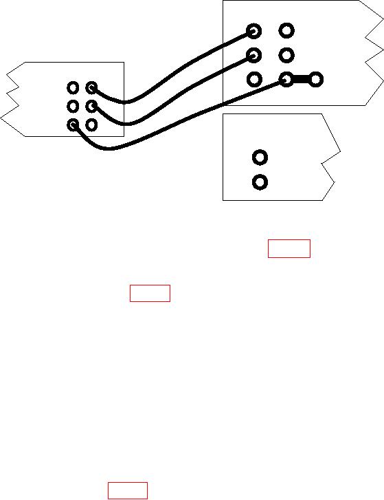
CALIBRATOR
OUTPUT SENSE
HI
HI
MULTIMETER
LO
LO
SENSE INPUT
HI
HI
HI
GUARD GROUND
LO
LO
CURRENT
GUARD
I
OUTPUT
HI
LO
AMPLIFIER
Figure 1. Dc and Ac Voltage.
(4) Set calibrator to (m) V dc outputs listed in table 1.
Record multimeter
indications in space produced.
NOTE
The values listed in table 1, Limits (V) column, are calculated
for maximum resolution of appropriate range, for example a
100 mV input should be read on multimeter 100 mV range.
The first measurement for each perimeter may not auto range
properly. If this occurs set multimeter to appropriate range,
then set back to auto range.
(5) Set calibrator to STANDBY, then press RESET pushbutton.
e. Ac Voltage. Calibrator, Fluke, Model 5720A/( ) Multimeter, Agilent, Model 3458A;
and Amplifier, Fluke, Model 5725A/( ).
CAUTION
Model 3458A maximum input: 707 V rms.
(1) Press multimeter FUNCTION/RANGE ACV pushbutton; then set calibrator to
(m) V, (k) Hz outputs listed in table 1. Record multimeter indications in space provided.
(2) Set calibrator to STANDBY, then press RESET pushbutton.
f. Dc Current. Calibrator, Fluke, Model 5720-A/( ), Multimeter, Agilent, Model
3458A and Amplifier, Fluke, Model 5725A/( ).
6

