
TB 9-4931-700-50
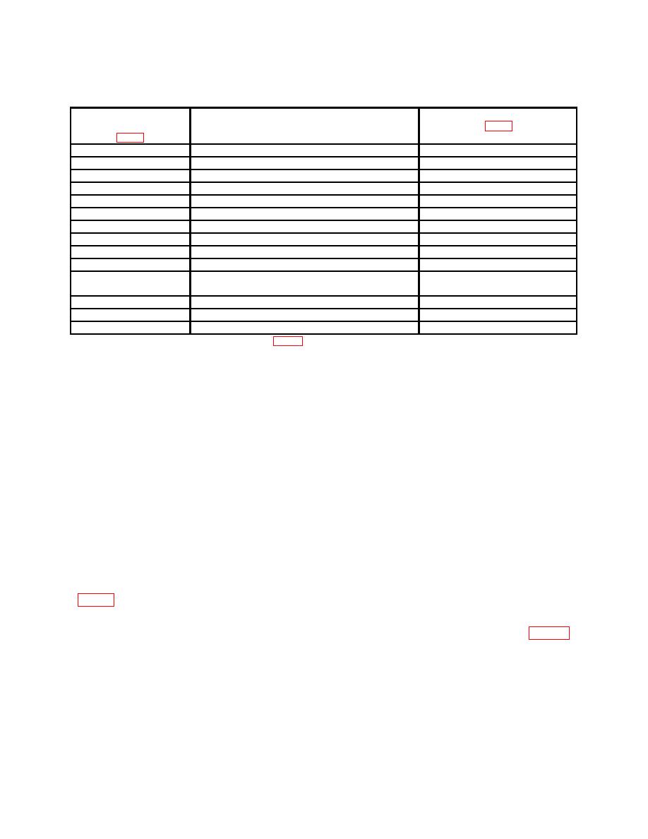
Test Instrument
Ac/dc Voltmeter, Frequency Counter,
Adjustments
Connection Points
or Oscilloscope
Indications
A8TP4
+69.50 to +70.50 V dc
A8434 (R)
A8TP1
-24.80 to -25.20 V dc
A8429 (R)
A8TP2
+5.10 to +5.30 V dc
A8R6 (R)
A4TP1
-0.0030 to +0.0030 V dc
A4R8 (R)
A3TP11
-0.0010 to +0.0010 V dc
A3R34 (R)
A2 PIN 122
450 to 550 ms sample gate
A3410 (R)
A25013
-0.0010 to +0.0010 V dc
A2R9 (4)
A2TP24
+0.550 to +0.650 V dc
A2R34 (R)
A2TP3
-0.0001 to +0.0001 V dc
A2R67 (R)
A2TP45
-0.90 to -1.10 V dc
---
A2TP46
Indication equal to that recorded in footnote 5
A4439 (R)
below
A1A3TP57
499 to 501 Hz
A1A4R5 (R)
A1A3TP58
-9.89999 to -9.90001 V dc
A1A3R32 (coarse), R34 (fine) (R)
A1A3TP59
+9.89999 to +9.90001 V dc 10
A1A3R14 (coarse), R16 (fine) (R)
1Adjust
frequency to 50 kHz and set A1A4S1 (fig. 2) to +9.9 V position. Overload lamp may illuminate, this may be
expected when A1A4S1 is switched from 19.8 V position.
2Set A1A4S1 to 19.8 V position; connect oscilloscope (A7), using cable (B4).
3Remove PC board A3.
4Reinstall PC board A3 and reset frequency to 50 kHz.
5Press FREQUENCY RANGE X1K pushbutton. Record voltage level indication.
6Press FREQUENCY RANGE X100 pushbutton
7Connect frequency counter (A5).
8Set A1A4S1 to -9.9 V position.
9Set A1A4S1 to +9.9 V position.
10After completing check, set A1A4S1 to 19.8 V position.
14. Power Supply (Model 746A)
NOTE
Do not perform power supply check if all other . parameters
are within tolerance.
a. Performance Check
(1) Connect ac/dc voltmeter (A1) between -30 V test point (TP3) of A4 assembly
V dc.
(2) Connect ac/dc voltmeter between +6 V test point (TP1) of A4 assembly (fig. 10)
and circuit ground. Ac/dc voltmeter will indicate between 5.94 and 6.06 V dc.
(3) Connect ac/dc voltmeter between +150 V test point (TP2) of A4 assembly (fig.
10) and circuit ground. AC/dc voltmeter will indicate between 145.5 and 154.5 V dc.
b. Adjustments. No adjustments can be made.
30

