
TB 9-5210-207-50
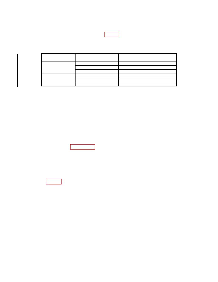
(4) Using the dimensions listed in table 3, verify the TI micrometer head at each
checkpoint. If the TI does not indicate zero (0) 0.0002 in. (or zero 0.0005 in. for TI's
without vernier), perform b below.
Micrometer head
Equivalent gage block stacks
checkpoint (in.)
between end stops (in.)
1/2
in. micrometer
0
1.500
head movement
.250
1.750
.500
2.000
1 in. micrometer
0
2.000
head movement
.500
2.500
1.000
3.000
b. Adjustments
(1) Tighten slotted nut on TI to remove any backlash.
(2) Zero set TI micrometer head at its minimum size in accordance with the
manufacturer's instructions.
9. Length Calibration
a. Performance Check
(1) Verify each extension rod and/or caps in combination with micrometer head,
using the techniques in paragraph 8 a (1) through (3) above. Verify only the minimum
indication for each combination.
(2) The gage block dimensions used to verify each setup must be equal to the
minimum length of the extension rod, micrometer head, and end-cap combination (size
marked on each extension rod) to be verified.
(3) The permissible error in length will not exceed the applicable tolerances
specified in tables 4 through 10.
THIS AREA LEFT BLANK INTENTIONALLY
8 CHANGE 1
PIN: 010260-001

