
TB 9-5210-218-40
TI
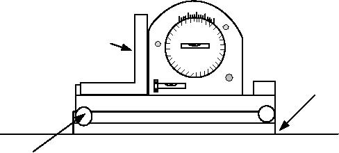
ANGLE
PLATE
SURFACE
PLATE
SINE PLATE
SINE PLATE
PIVOT POINT
Figure 1. Angle indication 45 degrees equipment setup.
(2) Release the knurled stud (ensure the knurled lock pin is in the lock position),
rotate the outer circle until the center bubble level indicates a level position. Tighten the
knurled stud to the outer circle.
NOTE
To calculate height of gage blocks needed, take the sine of the
angle and multiply it times the length of the sine bar. For
example: 45 angle, sin of 45, 0.707106 times length of the sine
plate, 10 inches equals 7.0711.
(3) Select and wring together enough gage blocks to give a height of 7.0711 inches
for a 45 degrees angle. Place the gage blocks under the sine plate bar and lower the
working surface to make firm contact.
(4) Place the protractor (clamped to the angle plate) on the sine plate. Release lock
pin and rotate protractor inner circle until bubble indicates a level position.
(5) TI must indicate 45 1 minor division on the vernier.
b. Adjustments. No adjustments can be made.
9. Edge Square Calibration
a. Performance Check
NOTE
Always locate TI in the same footprint on reference surface
when changing TI position. Each time TI is relocated, allow at
least 10 seconds settling time before taking a reading.
(1) Return the sine plate to 0.

