
TB 9-5210-219-40
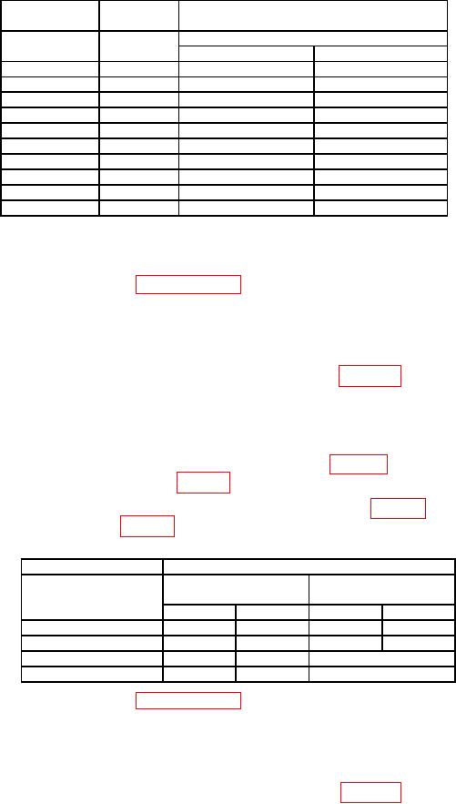
Table 4. Angle Indication
Test instrument1
Index table
Gage
blocks
Applied angle
Stack size
Limits (degrees)
(degrees)
(in)
Min
Max
5
0.872
4.9 (4.9)
5.1 (5.1)
-5
0.872
-5.1 (-5.1)
-4.9 (-4.9)
15
2.588
14.9 (14.7)
15.1 (15.3)
-15
2.588
-15.1 (-15.3)
-14.9 (-14.7)
30
5.000
29.9 (29.5)
30.1 (30.5)
-30
5.000
-30.1 (-30.5)
-29.9 (-29.5)
45
7.071
44.9 (44.3)
45.1 (45.7)
-45
7.071
-45.1 (-45.7)
-44.9 (-44.3)
59
8.5717
58.7 (N/A)
59.3 (N/A)
-59
8.5717
-59.3 (N/A)
-58.3 (N/A)
1 Indications in parenthesis are for models with 45 degree range.
(12) Remove gage block stack and TI from sine plate.
b. Adjustments. Perform paragraph 15 below.
10. Over Range
a. Performance Check
(1) If not already done, setup equipment as shown in figure 2.
(2) Ensure TI is parallel to vertical face of angle plate.
TI must be secured to
prevent movement.
(3) Beginning with index table set to a 0 degree starting point, slowly rotate index
table toward and then past first corresponding value in table 5. If TI indication is not
within limits specified in first row of table 5, perform b below.
(4) Repeat technique of (3) above for remaining value in table 5. If TI indication is
not within limits specified in table 5, perform b below.
Table 5. Over Range
Index table
Test instrument
Limits
Limits
Applied angle
(45 degree range)
(60 degree range)
(degrees)
Min
Max
Min
Max
45
50
60
N/A
N/A
315
300
310
N/A
N/A
60
N/A
N/A
>60
300
N/A
N/A
<300
b. Adjustments. Perform paragraph 15 below.
11. Over Range (Alternate Method)
a. Performance Check
(1) If not already done, setup equipment as shown in figure 1.
(2) Use precision level to level sine plate length and width to within 10 arc-sec.

