TB 9-5855-1890-35
7. Equipment Setup
NOTE
HIGH VOLTAGE is used or exposed during the performance
of this calibration. DEATH ON CONTACT may result if
personnel fail to observe safety precautions. REDUCE
OUTPUT(S) to minimum after each step within the
performance check where applicable.
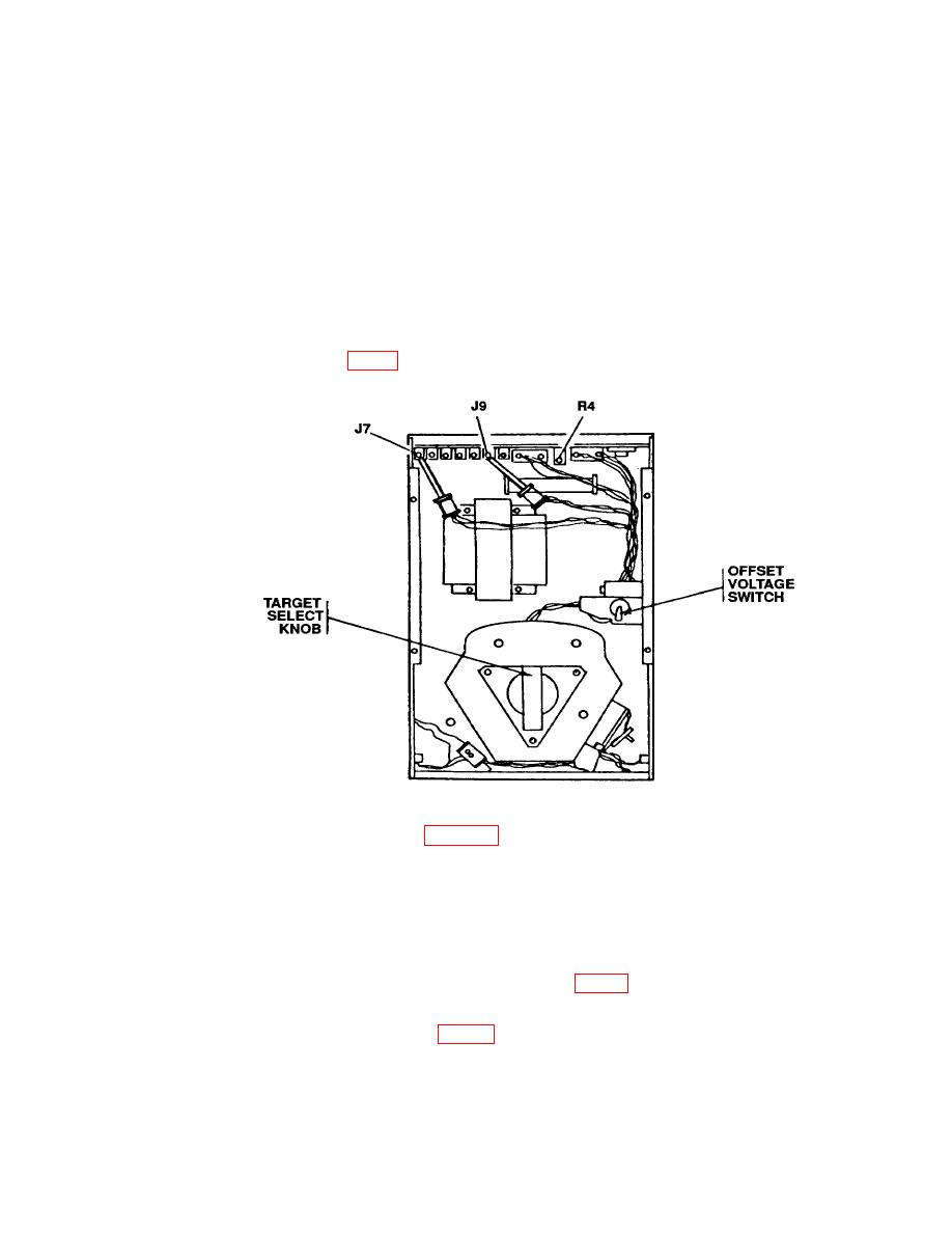
a. Remove external cover and internal shroud from TI.
(1) Install thermocouple mounting post (pair) on base of TI (approximately center
of second slot pair from exit port).
(2) Clamp differential thermocouple set (pair) in laboratory clamps and install on
thermocouple mounting posts, using mounting post clamps.
d. Using cotton tip applicator wood end, daub a small amount of thermally
conducive paste on the extreme bottom of heater plate (fig. 3) on front of temperature
controller.
thermally conductive paste.


