
TB 9-5985-313-40
9. Input Calibration Factor
a. Performance Check
(1) Set RF power amplifier and signal generator outputs to minimum.
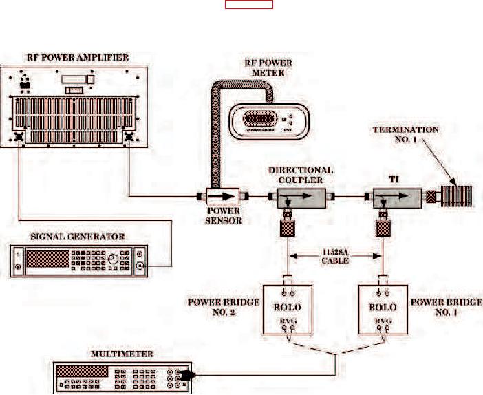
(2) Connect equipment as shown in figure 3.
Figure 3. Input Calibration factor - equipment setup.
(3) Adjust each power bridge divider dials for a null on OUTPUT VOLTAGE
meter. The meter pointer does not have to be on ZERO, only stopped on scale. Some drift
may be noticed after null is obtained.
(4) Set function switch on each power bridge to RVG (fully ccw).
(5) Measure voltage at RVG terminals of each power bridge, using multimeter.

