
TB 9-6130-285-24
11. Ripple and Noise Calibration
a. Performance Check
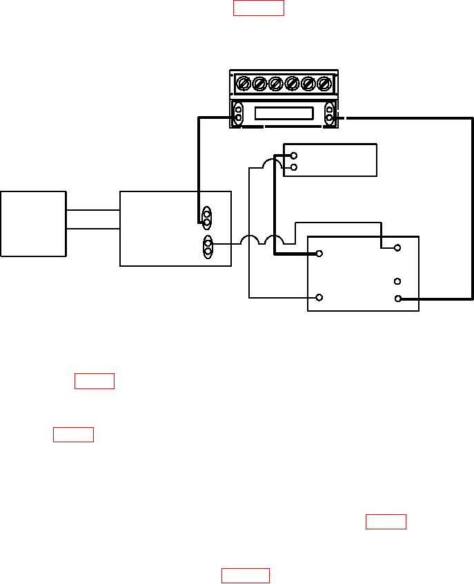
(1) Connect equipment as shown in figure 4. To measure constant current rms
ripple, connect the True RMS Voltmeter. To measure constant current p-p ripple, connect
the oscilloscope.
DECADE RESISTOR
HI
LO
TRUE RMS VOLTMETER
TI
OR
OSCILLOSCOPE
+S
COM
-S
OUT
AUTOTRANSFORMER
POTENTIAL
100 A
10 A
COM
DC CURRENT
SHUNT
Figure 4. Ripple and noise calibration constant current.
(2) Set the decade resistor resistance for maximum current at maximum voltage
from ratings in table 1.
(3) Adjust the autotransformer for a meter indication of 115 V ac.
(4) Using TI front panel controls, program voltage and current outputs for full scale
output (see table 1).
(5) Reduce the decade resistor resistance until TI front panel display indicates full
scale and ensure CC enunciator is illuminated.
(6) Divide the True RMS Voltmeter or Oscilloscope indication by the DC current
shunt certified resistance and record results.
(7) The results obtained in step (6) above must indicate within table 1 CC
Noise/Ripple limits.
(8) Using TI front panel controls, program voltage and current outputs for 0.
(9) Connect equipment as shown in figure 5. To measure constant voltage rms
ripple, connect the True RMS Voltmeter. To measure constant voltage p-p ripple, connect
the oscilloscope.

