
TB 9-6625-086-35
(8) Repeat (1) through (7) above with 100 ohm thermistor mount (A8) connected to
the TI and with the TI MOUNT RES switch set to 100Ω.
(9) Reconnect the 200-ohm thermistor mount to the TI and set the MOUNT RES to
200Ω.
mean value. No adjustment can be made on model 431B.
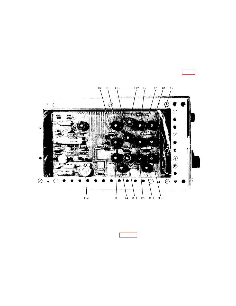
Figure 3. Left interior view, model 431C.
11. Range and Tracking Check Without Power Calibrator
a. Performance Check
(1) Connect the equipment as shown in figure 4.
(2) Set resistance decade (A7) to 10 kΩ. This 10 kΩ value can be decreased as
necessary to obtain full scale indication on TI.
(3) Set resistance decade (A6) to 1000 ohms.
9

