
TB 9-6625-1062-24
(6) The capacitance/inductance measuring system value will not be greater than the
proceed to (7) below.
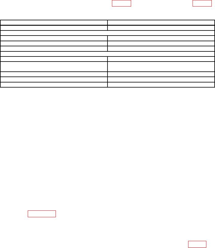
Table 3. Zero Capacitance
Test instrument
Zero capacitance (Pf)
ZM-59/U (Sprague 283W2)
30
Cornell-Dubilier, Model
CDA-5
---
CDB-5
---
CDB-3 (MX-198-U)
---
General Radio, Types
1419B
---
1419M (MX-4618/U)
35 for two terminal
16 for three terminal
1419A (MX-9266)
---
219K
46
219M
44
(7) Turn TI to first position indicated in appropriate table for model being calibrated.
(8) Capacitance/inductance measuring system will indicate within limits specified
in appropriate table below.
(9) Repeat technique of (7) and (8) above for remaining TI switch positions on model
being calibrated.
(10)Connect TI to capacitance bridge.
(11)Set capacitance bridge for three-terminal operation and measure capacitance.
Record value as lead capacitance.
NOTE
Perform (12) through (21) below for General Radio, Type 722-D
and (17) and (22) through (33) below for General Radio, Type
1422-D.
(12) Connect capacitance bridge to 115 and LO terminals of TI.
(13) Adjust TI for indication of 250 on dial. Measure capacitance and record value.
(14) Subtract value recorded in (11) above from value in (13) above. Calculated value
will be within 0.08 pF of previous test report value. Record value obtained on new test
report (See appendix A).
NOTE
Round off corrected value to two decimal places.
(15) Repeat technique of (13) and (14) above at each remaining low range dial setting
listed on the test report. Values will be within the tabulated tolerances listed in table 4 of
previous test report values.
8

