
TB 9-6625-1097-35
8. Frequency Accuracy
a. Performance Check
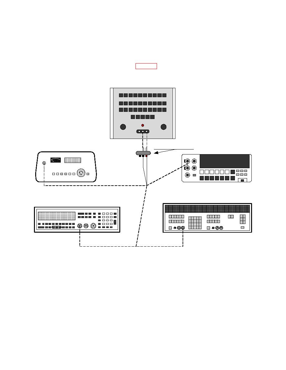
(1) Connect equipment as shown in figure 1, CONNECTION A.
TEST INSTRUMENT
0
1
2
3
4
5
6
7
8
9
0
1
2
3
4
5
6
7
8
9
0
1
2
3
4
5
6
7
8
9
VERNIER
AMPLITUDE
VOLTAGE DIVIDER
TRUE RMS VOLTMETER
B
N
O
TI
EC
NN
CO
CONNECTION C
AUDIO ANALYZER
FREQUENCY COUNTER
CONNECTION D
CONNECTION A
(2) Position controls as listed in (a) through (f) below:
(a) X10 CPS MULTIPLIER pushbutton pressed.
(b) 1 FREQUENCY DIGITS 1ST pushbutton pressed.
(c)
0 FREQUENCY DIGITS 2D pushbutton pressed.
(d) 0 FREQUENCY DIGITS 3D pushbutton pressed.
(e) AMPLITUDE control to midposition.
(f)
VERNIER control to CAL.
4

