
TB 9-6625-1097-35
(3) Frequency counter will indicate between 9.9 and 10.1 Hz.
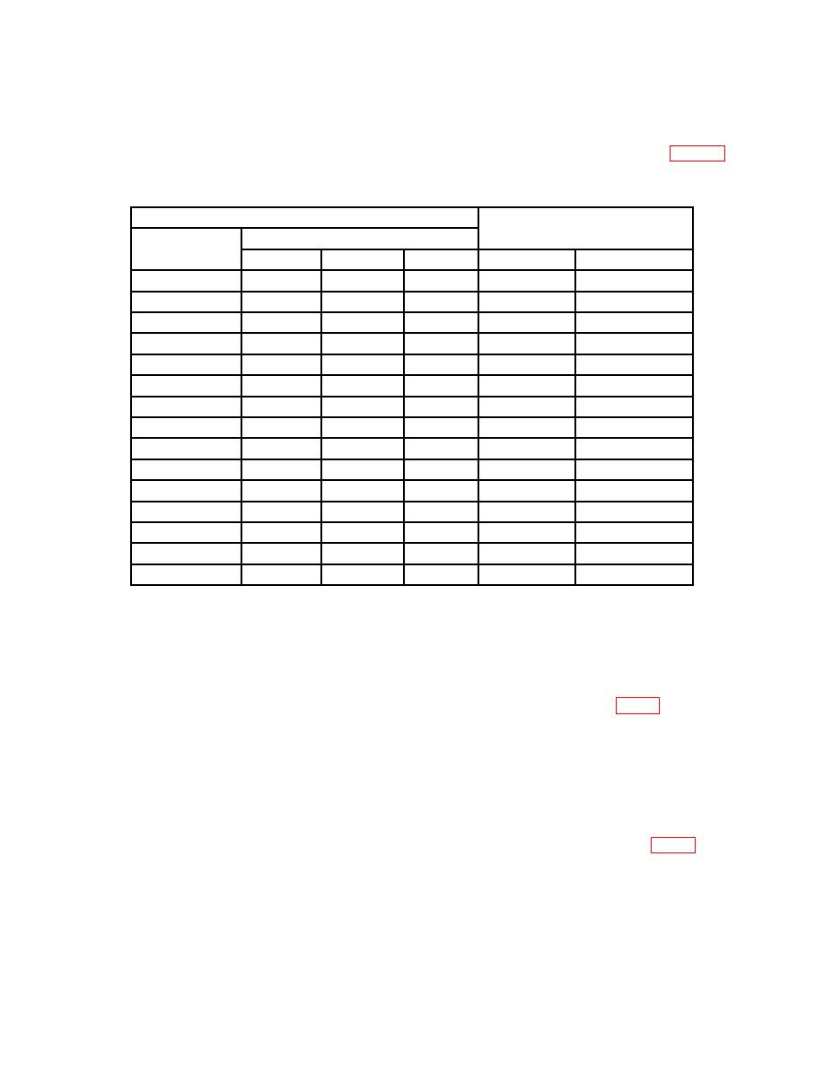
(4) Press MULTIPLIER and FREQUENCY DIGITS pushbuttons as listed in table 3.
If frequency counter indications are not within limits specified, perform b below.
Frequency counter indications
Test instrument pushbutton settings
(Hz)
FREQUENCY DIGITS
MULTIPLIER
1ST
2D
3D
Min
Max
X10 CPS
5
0
0
49.5
50.5
X10 CPS
9
0
0
89.1
90.9
X100 CPS
1
0
0
99
101
X100 CPS
5
0
0
495
505
X100 CPS
9
0
0
891
909
X1 KC
1
0
0
990
1010
X1 KC
5
0
0
4950
5050
X1 KC
9
0
0
8910
9090
X10 KC
1
0
0
9900
10,100
X10 KC
5
0
0
49,500
50,500
X10 KC
9
0
0
89,100
90,900
X100 KC
1
0
0
99,000
101,000
X100 KC
5
0
0
495,000
505,000
X100 KC
9
0
0
891,000
909,000
X100 KC
9
9
9
989,010
1,008,990
(5) Adjust VERNIER control fully cw. Frequency counter will indicate at least 1 MHz.
b. Adjustments
(1) Press 1.00 FREQUENCY DIGITS pushbuttons and X100 KC
MULTIPLIER pushbutton.
(3) Adjust C112 and C130 alternately for frequency counter indication of 100.2 kHz
and true rms voltmeter indication of 115 mV (R).
NOTE
Frequency will decrease by approximately 0.2 percent when
protective covers are reinstalled.
frequency counter indication of 902 kHz (R).
NOTE
Frequency will decrease by approximately 0.2 percent when
protective covers are reinstalled.
5

