
TB 9-6625-1176-24
(2) Position controls as listed in (a) through (j) below.
PERIOD 1 -10 pushbutton pressed.
(a)
PERIOD VERNIER dial to 10.
(b)
PULSE POSITION 10n-.1 pushbutton pressed.
(c)
PULSE POSITION VERNIER dial to 10.
(d)
DUTY CYCLE % pushbutton released (out).
(e)
WIDTH 25n-.1 pushbutton pressed.
(f)
WIDTH VERNIER dial to 2.5.
(g)
AMPLITUDE 10-30 pushbutton pressed.
(h)
AMPLITUDE VERNIER dial to 3 (30V).
(i)
INT LOAD pushbutton pressed.
(j)
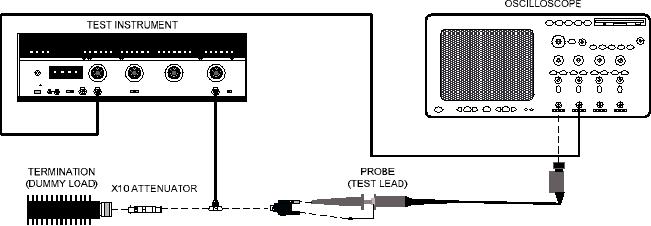
Figure 3. Equipment setup - pulse width and duty cycle.
NOTE
If an out-of-tolerance condition is noted in (3) through (27)
below, perform b below.
(3) Adjust controls of oscilloscope to display 1 pulse of TI output. Pulse width will
be between 21.5 and 33.5 ns.
(4) Set WIDTH VERNIER dial to 10. Pulse width will be between 89 and 116 ns.
(5) Press WIDTH .1 -1 pushbutton. Pulse width will be between 0.890 and 1.115 s.
(6) Set WIDTH VERNIER dial to 1. Pulse width will be between 80 and 125 ns.
(7) Press PERIOD .1 -1 pushbutton and set PERIOD VERNIER dial to 3.
Adjust oscilloscope controls to display 1 period of TI output.
(8) Slowly increase WIDTH VERNIER dial until oscilloscope display disappears.
Oscilloscope display will disappear at a duty cycle of 50 percent or greater (pulse width of
150 ns or greater).
(9) Position controls as listed in (a) through (c) below:
(a) WIDTH 25n-.1 pushbutton pressed.
(b) AMPLITUDE 30-100 pushbutton pressed.
(c) AMPLITUDE VERNIER dial to 10 (50V).
10

