
TB 9-6625-1200-24
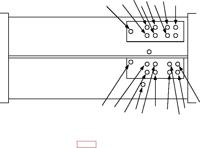
C6C
C3C
C8B
C12
C4C
C5C
C5B
C4B
R35
1
INCLUDED ON MODELS WITH S/N
C105B
C104B
C112
20,000 AND BELOW
1
C114
C104C
C106B
C105C
C103C
C103B
C106C
Figure 1. Test instrument bottom view.
(8) Repeat technique of (1) through (5) and (7) above for CH 2 VOLTS/DIV switch
settings and adjustments listed in table 5.
(9) Set oscilloscope calibrator to standby.
b. Adjustments. No further adjustments can be made.
10. Magnifier Registration
a. Performance Check
(1) Connect oscilloscope calibrator SOURCE/MEASURE CHAN 1 output to TI CH 1 input.
(2) Set oscilloscope calibrator MARKER output to .5 ms.
(3) Position controls as listed in (a) through (h) below.
(a) CH1-CH2 mode switch to CH1.
(b) CH 1 VOLTS/DIV switch to .5
(c) TRIGGERING source switch to CH1.
(d) TRIGGERING coupling switch to AC.
(e) TIME/DIV switch to 1 mSEC and VARIABLE control to CAL.
(f) TRIGGERING LEVEL control for stable display.
(g) Pull out X10 MAG switch.
(h) Adjust horizontal POSITION control to align first time marker to center
vertical graticule line.

