
TB 9-6625-128-24
8. Vertical Sensitivity
a. Performance Check
(1) Connect oscilloscope calibrator SOURCE/MEASURE CHAN 1 output to TI CH 1
input connector, and oscilloscope calibrator SOURCE/MEASURE CHAN2 output to TI
CH 2 input connector.
(2) Set oscilloscope calibrator to a voltage output of 5 mV and frequency of
1 kHz.
(3) Adjust oscilloscope calibrator knob located below the EDIT FIELD key for 5
divisions displayed on TI CRT. If Err displayed on oscilloscope calibrator is not within
limits shown in the first row of table 3, perform b below.
(4) Repeat technique of (2) and (3) above for CH1 with settings listed in table 3
below. Err displayed on calibration generator will be within tolerance listed.
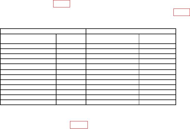
Table 3. Vertical Deflection.
TI
Oscilloscope calibrator
VOLTS/DIV
Deflection
VOLTAGE
Err display
(Div)
settings
(%)
1
mV
5
5
mV
3.0
2
mV
5
10
mV
3.0
5
mV
4
20
mV
3.0
10
mV
5
50
mV
3.0
20
mV
5
0.1
mV
3.0
50
mV
4
0.2
mV
3.0
0.1
V
5
0.5
V
3.0
0.2
V
5
1
V
3.0
0.5
V
4
2.0
V
3.0
1
V
5
5.0
V
3.0
2
V
5
10.0
V
3.0
5
V
4
20.0
V
3.0
(5) Set oscilloscope calibrator to standby and select oscilloscope calibrator CHAN 2.
(6) Set CH1-CH2 mode switch to CH2 and Trigger Source to CH2. Repeat
technique of (2) thru (4) above using table 3. If not in tolerance in (4) above, perform b
below.
(7) Set oscilloscope calibrator to standby.
b. Adjustments. No adjustments can be made.
9. Vertical Bandwidth
a. Performance Check
(1) Set the TI VOLTS/DIV (both) to 2 mV.
(2) Set the oscilloscope calibrator for a 50 kHz leveled sine wave at 12 mV p-p into
50 Ω feedthrough to TI CH 2 input connector. Set the oscilloscope calibrator to operate.
Adjust the output to obtain 6 div of vertical deflection on the TI CRT.

