
TB 9-6625-134-24
(9) Set calibrator as listed in (a) through (c) below.
(a) 4.243, m, V, ENTER.
(b) 5, 0, Hz, ENTER
(c) OPR/STBY to OPR.
(10) Rotate calibrator knob to adjust amplitude for 6 divisions of deflection on TI. If
calibrator does not indicate within limits specified in first row of table 4, perform b below.
(11) Repeat technique of (8)(o), (9)(a) and (10) above for settings listed in table 4. If
calibrator does not indicate within limits specified in table 4, perform b below.
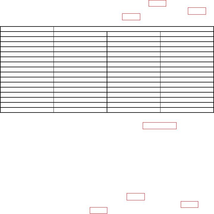
Table 4. Vertical Accuracy ACV Input B.
TI
Calibrator
Range (V)
Initial setting (V)
Minimum (V)
Maximum (V)
2m
4.243 m
4.063 m
4.422 m
5m
10.607 m
10.313 m
10.900 m
10 m
21.213 m
20.626 m
21.800 m
20 m
42.426 m
41.253 m
43.600 m
50 m
106.066 m
103.132 m
109.001 m
100 m
212.132 m
206.263 m
218.001 m
200 m
424.264 m
.412526
.436002
500 m
1.060660
1.031315
1.090005
1
2.121
2.063
2.180
2
4.243
4.125
4.360
5
10.607
10.313
10.900
10
21.213
20.626
21.800
20
42.426
41.253
43.600
50
106.066
103.132
109.001
100
212.132
206.263
218.001
(12) Reduce calibrator output to minimum.
b. Adjustments. Perform entire alignment procedure in paragraph 18.
9. Oscilloscope Readout Accuracy
a. Performance Check
(1) Ensure calibrator OUTPUT HI and LO is connected to TI INPUT B.
(2) Set calibrator output to 0 mV and OPR.
(3) Press TI keys as listed in (a) and (b) below.
(a) Using mV RANGE V set the Input B sensitivity to 2 mV/div.
(b) Using MOVE move the Input B ground level to the center grid line.
(4) Set calibrator to 6 mV and output to OPR.
(5) If TI B readout is not within limits listed in table 5 perform b below.
(6) Repeat technique of (3)(b), (4) and (5) above for remaining rows in table 5. If TI
B readout is not within limits listed in table 5 perform b below.

